Continue to Site

Eng-Tips is the largest engineering community on the Internet

Intelligent Work Forums for Engineering Professionals

  • Congratulations KootK on being selected by the Eng-Tips community for having the most helpful posts in the forums last week. Way to Go!

Torsional Constant of a Reinforced Steel Beam 2

Status
Not open for further replies.

MelBWasHere

Structural
Oct 13, 2022
6
I have a 50ksi wide flange beam that I'm reinforcing with a 50ksi WT (welding the stem to the bottom flange of the wide flange).
I'm trying to check the LTB limit state of the member per AISC 360-16 Section F4.2, but am having trouble figuring out how to calculate the torsional constant, J.
I don't trust software, since every one that I've used has given me different answers for all section properties (varying by 2-4%, which I'm wary to accept), so I'd like to figure out how to do this by hand.
Would it be conservative to assume the torsional constants are additive?
 
Replies continue below

Recommended for you

See this thread: Link

Essentially the reason you get different answers from software is the solution for the torsion properties is finite element based so it will vary based on the mesh type and density. Some programs use the finite element approach for the the geometric properties also which will add some variance also.

For a book that addresses the calculation refer to Analysis and Design of Elastic Beams: Computational Methods by Walter Pilkey
 
2%-4% across a couple programs seems like a perfectly acceptable tolerance to me to use in calculations. Just design to .9 and don't worry about it.
 
RE: Celt83 - After reading the thread, that's what I was afraid of, but I understand. Thank you for the book reference, I'll take a look!

RE: WesternJeb - Yeah, 2-4% is't terrible, could be worse. Maybe I'm just an old soul and trust hand calcs more since I can see what I'm doing; software can be a black box sometimes, so I like to be as unreliant on it as possible. With the direction things are going in the world, I doubt I can hold out for much longer.

Thank you!
 
Mel, it is a conservative assumption to take the sum of the J's of each component.

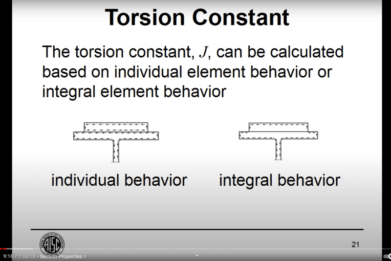
This AISC video gives a great explanation of integral behavior and individual behavior.
If you are using stitch welds it would be non-conservative to use the integral J.
In this case you want to use an effective J value, or conservatively use J individual.

This will make sense after you watch the video, skip to around 9 minutes into the video.

Screenshot_2023-12-21_150649_g2dgwg.png
 
AISC Steel Design Guide 9 has calculation methods for J

Tolerance on thickness and other dimensions of structural shapes will produce more than 2-4% variation of J, though...

design_guide_9_rap3mf.png
 
CDLD said:
If you are using stitch welds it would be non-conservative to use the integral J.
In this case you want to use an effective J value, or conservatively use J individual.

How would you go about finding an effecive J? Just weighting the J based on the combined J and individual summed J's at the stitch weld interval?
 
EngDM, I've never done it, I usually use the individual summed J's.
In the video I linked above, they provide a reference for calculating J with stitch welds and staggered stitch welds.
 
Use the sum of the J in a hand calc. You are unlikely to be able to efficiently determine the composite J of the cap plate and W section, and the cost to the owner of your engineering + the extra welding required is far in excess of the cost of a marginally bigger plate. The J component is less than half the elastic LTB resistance generally, and you are talking about a small variance in that.
 
canwesteng said:
Use the sum of the J in a hand calc. You are unlikely to be able to efficiently determine the composite J of the cap plate and W section, and the cost to the owner of your engineering + the extra welding required is far in excess of the cost of a marginally bigger plate. The J component is less than half the elastic LTB resistance generally, and you are talking about a small variance in that.

I'm more thinking for a joist reinforcing case. For the hat shapes we use round bar to reinforce, and I've developped a python code to calculate J of the combined shape, but theres no way I'm getting them to fully weld the entire length.

So the engineering cost is not that high, but the strength you can get out of properly calculating it can be significant.
 
CDLD said:
If you are using stitch welds it would be non-conservative to use the integral J. In this case you want to use an effective J value, or conservatively use J individual.

I believe those statements to be in error. I'm aware of what the guys say in the AISC video but I'm afraid that they've misinterpreted the reference that they supplied.

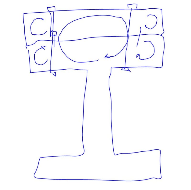
The efficiency factor described in the reference is about the location of the fastenings within the cross section and not whether the fastenings are stitch welded or not. Because bolts and rivets are inboard of the extreme edges of the combined section, you don't get full use of the big St. Venant stress hoops that one would want.

It is my belief that one does not need continuous welding in order to avail themselves of the integral J.

c01_me6mf4.jpg
 
Kootk, I must admit I haven't read the reference "Torsion of Plate Girders (Chang and Johnston 1952) until now, as I usually calculate J using the individual behavior.

Your comments about the bolt gauge are valid, as shown in the photo below.
Screenshot_2024-01-05_104517_wovaol.png


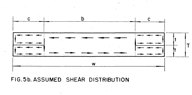
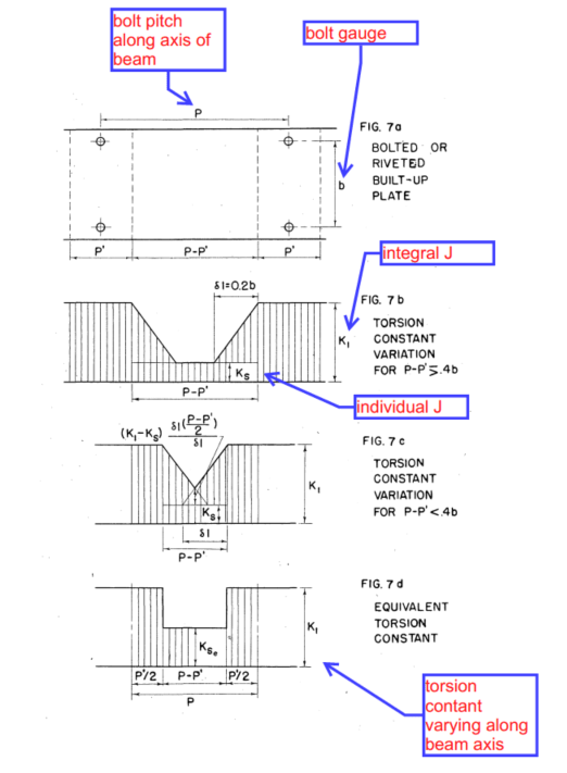
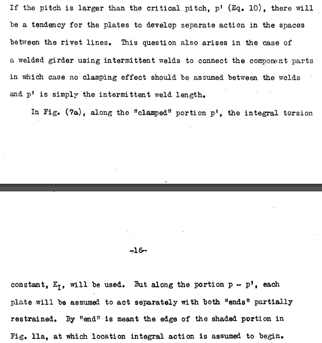
However, I believe the stich weld spacing or the rivet pitch (along the longitudinal axis of the beam) also effects the effective torsion constant of the beam.
I believe my comments earlier and the statements in the AISC video are valid.
Consider the figures below, taken from Pg. 15 of the reference.

Screenshot_2024-01-05_105554_iagggd.png

Screenshot_2024-01-05_105114_ufr6lc.png
 
Kootk, any thoughts on my reply above?
 
CDLD said:
Kootk, any thoughts on my reply above?

Thanks for the nudge, I've been meaning to return to this. I wanted to chase down another reference for you first but, seeing as that is holding up the show, I'll skip that and hope that I've earned your trust elsewhere somehow.

My thoughts are these:

1) My take on the section of the reference that you quoted is that its primary usefulness is in helping to inform designers on what an appropriate spacing for intermittent fasteners might be such that they don't have to worry about whether or not the integral J stuff has been compromised. As you can imagine, even 4W is going to be a very liberal stitch weld spacing in most flange plating applications where welds more like 2"@6" are the norm. That "notch of badness" in the reference sketches will quickly shrink into irrelevance at any practical stitch weld spacing I feel.

2) I feel that stitch weld applications wind up acting a bit like trusses from a stress field standpoint. The stresses tend to concentrate towards the welds and that is kosher so long as the angle of the faux truss webs don't get too aggressive. A 4W angled web would be very aggressive. A 1W web would be "normal" in the world of trusses and most weld patterns would go considerably lower than that. I've seen a highway girder publication where they studied the effect that lightly trussing a couple of deep highway girders has on the torsional stiffness of that system. It was a several thousand fold increase as I recall. I consider this to be meaningfully analogous to the situation that we're discussing here.

In summary, I stand by my previous assertions a) that no reduction need be taken for most practical situations and b) the guys in the video are out to lunch on this.

 
KootK said:
My take on the section of the reference that you quoted is that its primary usefulness is in helping to inform designers on what an appropriate spacing for intermittent fasteners might be such that they don't have to worry about whether or not the integral J stuff has been compromised.

Just took another look at the paper, if your intermittent bolt spacing is less than P' you can count on the integral J without reduction. If your bolt spacing is greater than P', technically your J will be less than the integral J.

For bolted assemblies, P' = A*T, where A = dia. of bolt head and T = total thickness of plate assembly
For intermittent welding, P' = weld length

For assemblies that are stitch welded you cannot get the full benefit of the integral J.

I haven't gone through a calculation to determine how much of a reduction you get using a 3-12 stitch weld (for example), but the point is the J you should be using for design is still less than the theoretical integral J.

For practicality, I like to use the individual J - maybe that's overly conservative, I don't know.
Seems like a better option than deciphering a paper from the 1950's.
 
See Case 26, Table 20, in Formulas For Stress and Strain, 5th Edition.
The main issue using this is that the corner fillet radius used in tabulating beam properties (assumed to be minimum radius) is apparently not the same as the tabulated k/k1 dimensions (assumed to be maximum values). Or maybe properties are tabulated based on elliptical fillets? Anyway, it is necessary to work backwards through moment of inertia equation to deduce fillet radius to use for other properties.
 
Status
Not open for further replies.

Part and Inventory Search

Sponsor