Continue to Site

Eng-Tips is the largest engineering community on the Internet

Intelligent Work Forums for Engineering Professionals

  • Congratulations SSS148 on being selected by the Eng-Tips community for having the most helpful posts in the forums last week. Way to Go!

Torsional Properties for I-Beam w/ a Cap Channel 1

Status
Not open for further replies.

jochav52802

Structural
Nov 28, 2018
81
Good Morning,

Per AISC's Design Guide-9, I've determined that an I-Beam installed in the field can't handle a torsional load that results fromm the supported joists being installed eccentrically by the contractor.

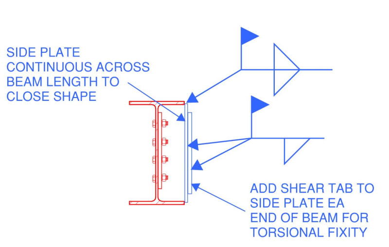
That said, I need to determine if adding a Cap-Channel to the bottom flange will be enough to provide the required torsional resistance.

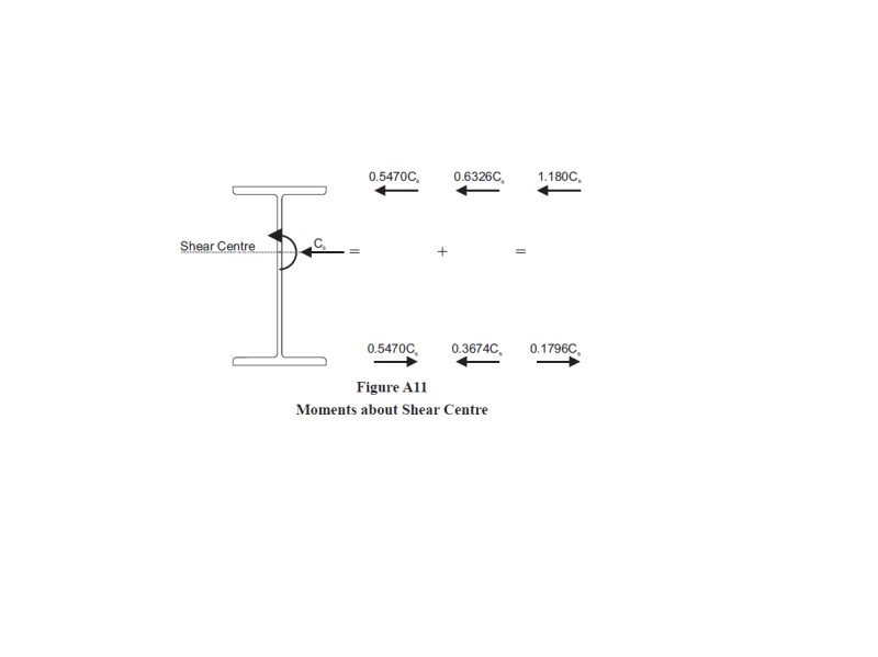
I found a CISC guide that shows me how to calculate J and Cw, but it doesn't tell me how to calculate Wns, which is the "normalized warping function." I'd appreciate if someone could help guide me towards a solution.

Many thanks in advance!

Best regards,

jochav52802
 
Replies continue below

Recommended for you

You might get the combined section to be strong enough but not stiff enough.
A WF with a cap channel is still an open section and very flexible torsionally.


Check out Eng-Tips Forum's Policies here:
faq731-376
 
Thanks JAE,

Should I consider welding a tube to the I-Section somewhere then? If so, what analysis approach should I take?

Thanks again!
 
One of the things that a cap channel does really well is crane rails. This is because what would have been a torsion in the wide flange becomes pure strong axis channel bending (due to the location of the channel's shear center). This cannot be said for other types of loading such as what you describe.

 
convert the channel as a plate, and then the composite member becomes a mono symmetric wide flange shape. you can find the formula to calculate the torsion properties of the member
 
Thanks JoshPlum,

Understood. We're just trying to find a quick way to reinforce the I-beam so that it is torsional strong/stiff enough to take the eccentric joist loads; I'm looking for the analysis procedure for checking an I-beam that's reinforced with a cap-channel.

Thanks!
 
Thanks Shu Jiang!

That makes sense, but I don't know how to find the equation for the "normalized warping function" specified in AISC's Design Guide-9, which is needed in order to determine the normal stress induced by warping. As ideas on how to calculate this?

Thanks!
 
Most ways of dealing with eccentric loads on open sections is:
1. Avoid the eccentricity
2. Provide external bracing to prevent twist in the section.

As JoshPlum observes, crane rail eccentric loading works well with a WF/Cap Channel configuration because the lateral crane load is generally aligned with the channel (which can resist the lateral force directly through its strong axis bending).

Check out Eng-Tips Forum's Policies here:
faq731-376
 
You might look HERE

Or HERE

Check out Eng-Tips Forum's Policies here:
faq731-376
 
Thanks JAE,

Understood, yet unfortunately, the eccentricity has already been introduced by the contractor, so I've been tasked with determining how to reinforce the section to ensure adequate strength/stiffness.

The only way I know to evaluate the torsion is per AISC's Design Guide-9, which requires the "normalized warping function" parameter that I mentioned previously; any help in determining how to calculate that or another method is appreciated!

Thank you!
 
Thanks JAE,

I found both of those papers too.

Unfortunately, I'm a new employee and not familiar enough with our structural analysis software to go the FEA route.

I'll look into the second option further, but I was hoping to find a simpler process than the one described therein.

Thanks again!
 
An alternative to JAE's #2 above. Not sure what would be more economical.

Capture_emdiey.jpg
 
Thanks cal91,

I thought of that too, but the contractor prefers to add a channel to eliminate overhead welds.

Thanks!
 
Yeah, the overhead welds are a pain but you could design it as a skip weld based on the loading.

If the contractor doesn't like the side plate solution I'd just go with JAE's #2.
 
Search key words "Torsional section properties of steel shapes" and you will find a document prepared by Canadian Institute of Steel Construction. the document lists the formula of torsion properties calculation for some steel shapes including Channel plus W section.
in another way, you can just assume channel plus half W section resist the lateral horizontal force. this will avoid the torsion analysis.
 
Thanks cal91,

Unfortunately, we can't use JAE's #2 option either as there is no room for torsional bracing.

Thanks Shu Jiang,

I've been using that CISC document to calculate J & Cw, yet it doesn't specify how to calculate the "normalized warping function" parameter required by AISC's Design Guide-9 for computing warping normal stresses.

Thanks!
 
I'd really go with the sideplate. A channel cap just isn't the right reinforcement.

Tell the contractor that he wouldn't have to do overhead welds if he hadn't installed the joists eccentrically.
 
Thanks cal91,

I'm with you; unfortunately, I've been asked to prove that a channel reinforcement won't work before they'll consider the plate option.

Thanks for your help!
 
I'd go with the side side plate like others have discussed above.

For proving the beam in torsion, I highly recommend this excellent reference catered towards designers. It has a lot of worked examples that should help you do the check quickly and efficiently.

If you have some experience with FE i.e. modelling shell structures I don't see why you can't do an FE analysis as a check. Model the beam using shell elements and make sure the load is applied at the correct location. Good for ticking off some CPD!

gl ukbridge
 
one way to get around normalized warping function calculation

Decompose the lateral force the top surface of the rail to a force applied to the member shear center and a torsion. The force can be decomposed to two forces on top and bottom flange of the member; the torsion can be decomposed a force couple and two opposite direction forces will be applied to top and bottom flange.
And then calculate the lateral force effect on bottom and top section separately.


xxxxx_gzst90.png
 
Status
Not open for further replies.

Part and Inventory Search

Sponsor