Eng-Tips is the largest engineering community on the Internet

Intelligent Work Forums for Engineering Professionals

total run out on a datum 1

Status
Not open for further replies.

DJ Nelson

Aerospace
Oct 2, 2023
7
0
0
US
We have a step pin the tolerancing seems to be incorrect.
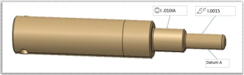
See Datum A on the Attachment they call out total run out of .0015 on datum A.
in sec 9.2 one part in the standard that resembles our pin we have it seems as if you can not applied Total runout to the datum.
In sec 9.4 the standard it gives another example were if you have multiple datums a significant length or axis separation.
We think they should maybe change the call out to either straightness or cylindricity.


Total_runout_pin_irgigf.jpg
 
Replies continue below

Recommended for you

Total runout or circular runout requires a datum feature reference. It does not appear you have that reference. If this is the basis datum feature for the rest of the part then cylindricity would be appropriate.

If you want to provoke people, use total runout and reference the same surface as the datum feature.
 
were trying to inspect the pins with our roundness machine
I am not sure what you mean by provoke we think we need to have a conversation with our tool designers.
We just wanted to run it by the forum first.
 
That method would fit with cylindricity.

As to "provoke," an example.

One ability of a parallelism tolerance is to control flatness of nominally flat surfaces.

If one said that a surface should be parallel to itself to control flatness instead of using flatness, inspectors would become angry.

Technically it, or self-referencing total runout to the datum feature the total runout would apply to, is allowed, but people like to think that if there is a datum reference one can grab that or fixture to it, but then that feature cannot be reached to inspect it and that means having to think hard about how to do so and no one wants to do that.
 
Based on this drawing, cylindricity is the appropriate callout for datum feature A. As Dave said, runout requires a datum reference and the total runout has no datum reference. To make things worse, you have a concentricity callout. What do you think the difference is between concentricity and runout such that you would use it instead of runout? I understand this may not be your drawing but whoever made it really needs some training. Almost none of it makes sense.

John Acosta, GDTP Senior Level
 
powerhound said:
....To make things worse, you have a concentricity callout. What do you think the difference is between concentricity and runout such that you would use it instead of runout? I understand this may not be your drawing but whoever made it really needs some training. Almost none of it makes sense.....


Why we are assuming that ASME is used b default? How do you know the OP is not using ISO GPS?
I am not questioning the incorrect runout callout, but I am questioning the "default" interpretation of the drawing as being an ASME drawing.
And by the way, I agree that the chances of this drawing being ASME is maybe 95% :) ---but I am still bother about it's "defaultness"....or jumping to conclusions....
 
Greenimi, the original question that started the thread mentioned 9.2 and 9.4. While that's not the current standard, an older versions (2009) shows Figures 9-2 and 9-4 might be what he/she is referring to.
 
I teach my metrology students that cylindicity is a runout of a cylindrical surface rotating on itself, while flatness is the parallelism of a part with regards to itself. It's counter intuitive but make sense as the datum of the cylindrical feature is not the surface itself but the axix of the Actual Mating Enveloppe of the surface.
 
Kinda harsh on concentricity. I believe it was pressure from big companies, the sort who build cars, as they had already outlawed it in their customization packets for lower tier suppliers. This means that they no longer have to argue with lower tier suppliers.

Concentricity serves as a control that cannot be duplicated by any other control except for round parts, just as symmetry cannot be duplicated by any other control except for simple shapes.

If it were universally possible, the addendum would have provided guidance. They do not because they cannot.

That said, it's not particularly valuable as presented in this image.

One place it is useful is in the likes of the s-cam used to operate air brakes on trucks. It is hugely important that the two cam surfaces match each other but not as important that they have an exact shape. Thanks for taking away the one control that can guarantee correct brake application without adding excess expense.
 
3DDave said:
One place it is useful is in the likes of the s-cam used to operate air brakes on trucks. It is hugely important that the two cam surfaces match each other but not as important that they have an exact shape.

3DDave,
Could you, please, provide more details? Maybe even a simple drawing. What do you mean by "two cam surfaces match each other"?

I've seen this video (or maybe others alike), but not sure how would you control the S-cam with concentricity?
Which is the datum feature and which are the controlled features?
 
The axis is determined from the bearing for the s-camshaft. You control it by specifying it. Each pair of opposing points need a center within some distance of the axis. The cam surfaces should be concentric to the shaft axis.
 
3DDave said:
The axis is determined from the bearing for the s-camshaft. You control it by specifying it. Each pair of opposing points need a center within some distance of the axis. The cam surfaces should be concentric to the shaft axis.

But those two pairs of "C" shapes have different centers so how concentricity could be used? I know the "classical" examples of concentricity the entire feature has only one axis/ center (not two like the ""S" cam).
I am sure I am missing something.
Could you, please, show a sketch on how your proposal looks like?

Just trying to learn a little more.........

 
Read the definition - those "C" shapes usually have a spiral of constant angle of increase and are not an arc. The center points of opposed locations on the cam as the mutual line that passes through the axis is controlled.
 
Thank you SeasonLee for your picture and for taking the time to make it. I really appreciate it.

Questions:
1.) How concentricity suppose to work in this case? Do we need 4 concentricity callouts, one for each section with the same radii? (one concentricity for R1, another concentricty for R2, and so on and so forth)
Or a stand alone / single concentricity callout would be enough to clearly show the design intent?
2.) What would be the advantage of using concentricity versus profile in between points ? (considering the transitions between radii are to be marked with points). Or even composite profile between points with the lower segment refining the relationship between opposing features with the same nominal radii (R1 and R5; R2 and R6; etc.)

What concentricity brings to the table and profile / composite profile doesn't?
Do we really "care" about center points of those features (the cam surfaces) or we really "care" more about the cam surfaces itself?

Again, just trying to understand more what are we missing now that the concentricity is gone.

Thank you guys

 
Profile controls the form. Concentricity doesn't. Concentricity is a refinement to other controls. ASME said that making the part with a more precise form than is required to get what concentricity provides is the only solution.

Why have position tolerance or angularity or runout or ... when making all surfaces with a profile of surface tolerance of 0.000001 would work just as well?

Whether one cares or not doesn't matter. What matters is whether concentricity is important to control a feature. ASME eliminated that control along with the planar version, symmetry.
 
Status
Not open for further replies.
Back
Top