Continue to Site

Eng-Tips is the largest engineering community on the Internet

Intelligent Work Forums for Engineering Professionals

  • Congratulations KootK on being selected by the Eng-Tips community for having the most helpful posts in the forums last week. Way to Go!

Total Runout - Long Shaft

Cup909

Mechanical
Nov 11, 2024
6
I'm looking to measure the total runout of a very long shaft along the entire length. A 1" diameter shaft, 5' long, with datums 3" from each end, and a total runout requirement of .005".

The traditional method would be to put the datums on Vee-blocks and roll it then drag the dial indicator up and down the shaft. A shaft of this length/diameter/support is going to sag more than the total runout. So how do you measure the total runout using traditional hand tools?

My strategy is as follows; First, constrain the diameter through measurement using snap/mic/etc. Then spin the shaft on rollers taking circular readings along the length of the shaft. A bend in the shaft will show up as circular runout at that spot. TLDR; total runout is circular runout as long as the form (diameter) of the part is constrained.

Does this strategy make sense?
 
Replies continue below

Recommended for you

I'm looking to measure the total runout of a very long shaft along the entire length. A 1" diameter shaft, 5' long, with datums 3" from each end, and a total runout requirement of .005".
How far will your shaft sag under load? If it sags significantly more than .005", how meaningful is your runout measurement?
 
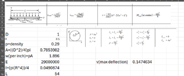
The deflection I calculate (screenshot below) for a 1" round, 5ft long at 54" datums (3" from either end), is a deflection of 0.147", so a significant amount and well out of tolerance to just ignore. That will be lessened slightly by the 3" cantilever on either end, but not near enough to counter the runout.

I'm using the 5' rod/1" round as a simple explanation. Real part is more complicated, with profiles, more end sticking out, etc. The calculated values (treating the smallest portion of the shaft as the rod) are within 20% of the as-measured.

1731356178871.png
 
OP
Is this engineering drawing requirements.
Has this shaft been heat treated.
Has it been straighten.
Total run out is a simple measurement on shafts between centers or ground datums.
 
Cheat and hang it vertically and lean it against the v-blocks.
 
Op
Generally an issue like this engineering drawing with state in
Restraint condition.
Open for discussion
 
Cheat and hang it vertically and lean it against the v-blocks.
I've seen varying CMM machines for hanging & measuring crankshafts, but most top out around 4-5'. Technically would work in my example, but the parts we're working on are turbine shafts at 9ft. At least I haven't seen one with the capability.

Hanging and taking the vertical measurements would work in theory, but I don't know how to calibrate a surface to run the indicator up and down.
 
OP
Is this engineering drawing requirements.
Has this shaft been heat treated.
Has it been straighten.
Total run out is a simple measurement on shafts between centers or ground datums.
This is an engineering drawing requirement. Turbine shaft, should be familiar to you. I didn't post the actual drawing/snippet for obvious reasons. I'm a supplier of the shaft.

Op
Generally an issue like this engineering drawing with state in
Restraint condition.
Open for discussion
I just reviewed the drawing and there isn't a callout for restraint condition or equivalent. They do have a general specification listed on the drawing for drawing interpretation, I'll dive into that tomorrow to see if there is a callout for restrained condition. I hadn't thought of that.
 
Op
Also in practice there will be bearing journals at each end and in the center of turbine shaft. It is permissible to add steady rest on those other bearing journals. Just be carefull
Not to scratch them.
 
I checked for any callout of restrained condition. Nothing like that in the general specification. Absent any sort of general specification, my interpretation is that it should be in the unconstrained condition. The customer explained that the runout condition is being controlled for installation practices and to control vibration caused by residual stresses during operation. Logic wise, this checks out to me.

Op
Also in practice there will be bearing journals at each end and in the center of turbine shaft. It is permissible to add steady rest on those other bearing journals. Just be carefull
Not to scratch them.

The datums are called out as the bearing journals. A mockup below. License server is acting up this morning, so, a master of powerpoint I am.

Since the datum line between two features is established by the vee-blocks, I don't think I can support the center of the shaft without over constraining the part. E.g; If I add a steady rest, I can make any bent part straight.

1731417120498.png
 
I'd hate to be the person who signed off on accepting this contract. This is going to cost way more than expected to deal with.

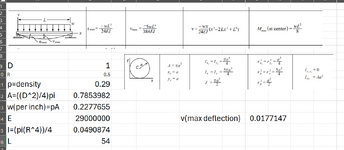
Also, note that there is an error in the calculation - W = rho * A; since rho and A are both less than 1, the product cannot exceed 1.

I calculated W = 0.227765467 lbf and vmax = -0.0177147 inches, still triple the allowable total runout.

When you say "customer" is that person from procurement or from engineering? Did they flinch when you mentioned the amount of sag?
 
Op
No not true, it is common practice to use a steady rest while turingand grinding. But where many manufactures lose it is during heat treating. If the heat treated does not take special procedures, it will distort like a noodle. Then the only option is peen straighten or straighten under a press. Do not grind or machine it until it has acceptable straightness.
.
The heat treated must hang vertical, and it must fit in the oven this way.
If it is stacked horizontal with distorted baskets , part will be like noodles. Sometimes is to distorted to straighten.
A fixed process iis required, and locked
This process needs to be developed.
Test samples need to be run, as not to scrap out the entire expensive lot.
I have done this many times.
You can not machin bend or distorted shafts with out straightening.
 
Op
Lay parts on a flat precise table like a inspection granite. Verify straightness.
The straightness must be better than
The allowable stock removal.
 
When machined in-house or from a vendor, can the straightness be held to the tolerance you call out?
 
I'd hate to be the person who signed off on accepting this contract. This is going to cost way more than expected to deal with.

Also, note that there is an error in the calculation - W = rho * A; since rho and A are both less than 1, the product cannot exceed 1.

I calculated W = 0.227765467 lbf and vmax = -0.0177147 inches, still triple the allowable total runout.

When you say "customer" is that person from procurement or from engineering? Did they flinch when you mentioned the amount of sag?

You're completely right on the W calculation. It wasn't setup as a formula! (Value matched actual part, not the 1" rod we're discussing.) Corrected it and my value matches yours. See below. Thanks for the catch.

Customer is the final customer, who initiated the contract to our company. There's not been a lot of flinching per se - it's more "Well, how do we compensate for the sag measurement?"

This is a new market space for us, I've been to shops who make these parts regularly and to the customer's facility where they manufacture & inspect. None of these shops are using advanced inspection equipment (CMMs, hanging equipment, etc.) to inspect the parts so there should be a way to address this outside of advanced equipment.** I'm in the process of formalizing an SOP for our inspection processes and writing the compensation out when I decided it's worth revisiting my logic.

**As far as advanced equipment goes - I've looked at various suppliers of ferro arm systems, laser systems, etc. None of them have the accuracy to actually measure this (confirmed by the suppliers). A traditional CMM should meet the requirement, but the part length makes that an expensive and painfully slow process. I'm adverse to buying a 10' long CMM.

1731422276969.png
 
CT
It is done often with shafts.
The issue shaft of this ratio Dia vs length are a pita. Processing engineer has to be very experienced.
 
Someone in your company accepted the contract. If all the values given are fictitious then I cannot help at all.

Use the method the customer claims to use.

Had this been circular runout, not much of a problem as the sag will make for an offset that is constant regardless of the turning of the shaft and will even out. Total runout, on the other hand, cannot stand to have a sag component.

If a pooch is involved that pooch is going to have puppies.
 
Having been an inspector myself I will say it is entirely possible (likely even) that the other shops are not inspecting this feature at all or using a half-measure just to verify it "seems ok enough" - 0.005" runout for that length is a bit over-the-top. Even if you had a 10ft CMM you'd have to hang it and probe all 360 degrees? Highly doubt that even the customer is doing that. I would ask the customer what they or the other shops are claiming to be doing, and then give it your best shot.
 
The issue is as stated before when a company large or small takes work that it is not suited for. It usually ends in scrap.
While .005 runout is a tough one and expect a 25-50% loss in parts as scrap. There is no magic wand that by inspection is going to resolve the issue. If the parts are out of tolerance and not enough stock was allocated or as I said before straightness is a must. It is what it is.
While proper Inspection methods are importsnt. Shafts must be on extra precision vblocks or between centers to in spect run out.
 
What about weighing and measuring the dimensions of the part and calculating the sag at the center based on that, then subtracting the deflection value from the measured total runout?
 

Part and Inventory Search

Sponsor