Eng-Tips is the largest engineering community on the Internet

Intelligent Work Forums for Engineering Professionals

  • Congratulations waross on being selected by the Tek-Tips community for having the most helpful posts in the forums last week. Way to Go!

Transfer Column Settlement 2

Status
Not open for further replies.

struggle66

Civil/Environmental
Jul 5, 2013
127
0
0
SG
Hi Good Day Everyone,

Capture_a4drs1.jpg


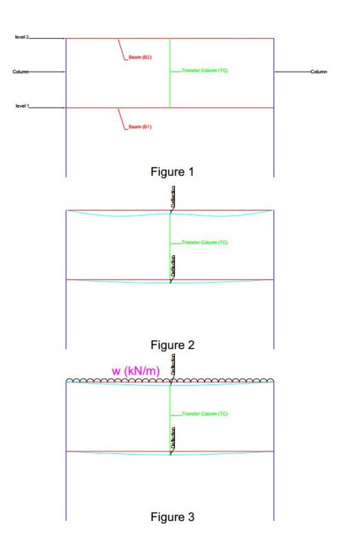
I have a transfer beam B1 as shown in fig 1. Deflection of B1 will cause settlement of B2 as shown in fig 2. Usually I simply control the deflection B1 <10~20mm.

My question is how do I consider and include this settlement effect in my B2 design? Convert this settlement deformation to moment? How do I convert?

As shown in fig 3, assume B2 as single span beam and derive back the moment that will cause this defection which is settlement @ transfer column)and add bottom bars at intermediate support according for that moment?

Thanks in advance for your time and help!
 
Replies continue below

Recommended for you

The deflection of B1=B2. The exact moment each will experience will be
a function of their relative stiffness. If EI of B2 > EI of B1 the larger moment
will be in B2 or vice versa. I think it will be quite difficult to analyze them individually and should rather be solved simultaneously.
 
struggle66,

Based upon your previous posts, are these beams to be post-tensioned?

I would analyse the full frame over its 2 levels, BUT, I would consider any staged construction, namely: lower columns with lower beam, then add upper columns with upper beam to the model, including any shoring that will remain in place under the lower beam PRIOR to construction and stripping of upper beam. Time-dependent effects may need to be considered depending on the magnitude of the loads, spans, and member size/s.
 
Thanks and sorry for late reply.

Honestly now I do not know how to analyse the full frame. I jsut have never done it. Any easy way or shortcut to analyze individually? Anyway I will give a try to analyse as a whole based on their relative stiffness.

Ingenuity yes those are post-tensioned.
 
What are the spans here? And the relative B1/B2 beam sizes? Is B2 continuous beyond the supports shown?

If you can keep B1 deflection down to 20 mm as you say, it may not even be necessary to worry about the support settlement for B2.

As far as accounting for the settlement in a simple manner, if your software will not model support settlement:

1) Design B2 for a case with no settlement.
2) Estimate the worst settlement you might get.
3) Model B2 as a long single span with C1 represented as an upwards reaction rather than a support.
4) Add a downwards point load to B2 at C1 until you get a deflection value matching your settlement and design for this condition.
5) Unfortunately, repeat steps 3 and 4 for each load case.


I like to debate structural engineering theory -- a lot. If I challenge you on something, know that I'm doing so because I respect your opinion enough to either change it or adopt it.
 
It is a simple support settlement problem for Beam B2.

Find the point load to cause a deflection of 20mm in beam B2 assuming it is a simple span beam without the central column. I would use about .5Ig to allow for cracking.

Calculate the Bending Moments for this point load on the simple beam.

Apply that as an extra bending moment diagram in the design of the 2 span B2 along with its other loads.

Or use a spring support for the centre support for beam B2 and calculate the spring stiffness based on the deflection performance of the transfer beam.
 
rapt, KootK, BA

Thanks that will be the easiest approach for me. I just wasn't sure :).

I think it is time for me to get familiar with more than one software.
 
Status
Not open for further replies.
Back
Top