Continue to Site

Eng-Tips is the largest engineering community on the Internet

Intelligent Work Forums for Engineering Professionals

  • Congratulations cowski on being selected by the Eng-Tips community for having the most helpful posts in the forums last week. Way to Go!

Transfer loads from wall

Status
Not open for further replies.

Gile_

Structural
Nov 13, 2020
37
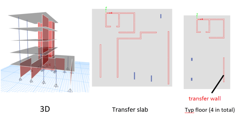
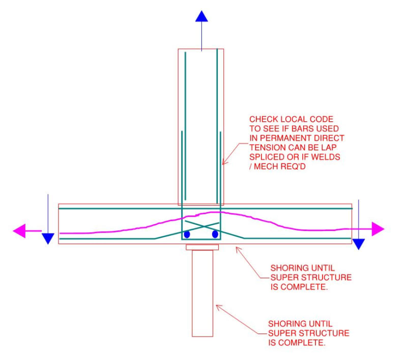
I am going to provide transfer load schedule for PT contractor and am wondering how you guys deal with the transfer gravity loads for walls? Do you simply gives line load or together with bending moment? I believe the wall will have great axial loads at ends due to bending moment.
Please see below simplified section as an example. (The arrangement is actually more complicated).
TF_xhnfla.png

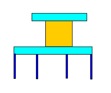
Please note that I am talking about gravity only here and it is a general question, not just limited to the example above.
 
Replies continue below

Recommended for you

Is your wall transferring large strong axis bending due to gravity loads? That seems odd.
 
I simply provide the axial load and associated bending moments on each primary load case, rather than tension/compression stresses. I let them do the rest.
 
- jayrod12
I got more than 1000kNm from my model. The span below the wall is a bit large. At the beginning I thought it was due to the 'truss effect' but then I did a load takedown, assigned the loads from isolated floor model of above structure to the transfer slab and the long term deflection of the transfer slab is not much. I also did the construction sequence in my full structure model and the moment is still there. Then I deleted the wall and replaced the wall with 2 columns at ends and assign the resultant axial loads to transfer slab and the long term deflection is still ok. So I am a bit confused whether to ignore the moment or not.
I will probably upload a model as an example later.

- Enhineyero
When you said axial load and associated bending moments, does that mean instead of transferring to line loads, you just provide the the axial point loads and bending moments for dead & live?
 
I have uploaded the model can anyone have a look if you use ETABS? Link

Please see below image for plan view and 3d model

full_wornn0.png


The moment in transfer wall under dead load is about 1700kNm.
mm_ghbnmd.png


I have run isolated floor model and get the axial loads (which is about 1500kN) and then applied to transfer slab model. The long term deflection of the slab is just about 6mm.
al_pkbbfo.png


So my question is. How do I provide the loads to PT contractor? Do I do 1500/5 = 300kN/m and ignore the bending moment? Is it safe to do so?

Your replies will be much appreciated!!
 
The wall transfers a non-uniform line load. It is very likely the program is only able to report wall centroid forces so you need to convert the centroid forces to a line load by a process similar to p/A +/- m/S, recommend checking the program manual.

My Personal Open Source Structural Applications:

Open Source Structural GitHub Group:
 
-Celt83
Yeah. That is what I was thinking and what I will do if I design the slab by myself. In fact, if you export from Etabs to Safe it will automatically give you multiple point loads with unequal value. But won’t it be impractical to provide loads in this way to PT contractor especially you need to specific the direction of the moment and associated local axis? How do you guys normally do? Normally I am comfortable with line load if the moment is small, hence my post.

Looking at the example I uploaded above, I feel like the problem is that the transfer wall sits on the support on one end and the mid span at the middle, making the wall behave like a cantilever to pick up the floor below which means the bending moment is due to this cantilever behavior? That said, I have run the long term deflection check on the transfer slab isolated model which is ok and even performed construction sequence on my full structure model (the moment is still there after the analysis). So if I don’t wanna use this moment (if my above ‘theory’ is correct) which is beneficial for the transfer slab but instead treat it like a normal line load, is it safe to do so for both slab and the transfer wall? Or is there anything that I need to do like the detailing etc?
 
Gile said:
(the moment is still there after the analysis)
I would find out how the software reports wall forces, reach out to their tech support. Again it is likely they are reporting centroid or top of wall forces in which case you need to perform a secondary analysis to determine the reactionary line load at the base of the wall. If wall forces are reported at the top then the secondary analysis is P/A +/- M/S +/- V*h /S, where V*h is the moment from the in-plane shear force.

Gile said:
So if I don’t wanna use this moment (if my above ‘theory’ is correct)
Your theory is not correct, the moment is integral in reporting the unbalanced reaction at the base of the wall panel. You can treat it as a line load but you must first determine the line load from all of the reported wall forces not just the axial load.


My Personal Open Source Structural Applications:

Open Source Structural GitHub Group:
 
What type of connection between wall and slab/column
Note walls seem unsymetrical may cause torsion in building in seismic for example
 
-Celt83
Sorry I didn’t know you have replied when I was editing my comments. So like I edited in my comments. The axial forces comes with top and bottom. In etabs you can assign wall as piers which produce resultant forces like columns. However, when you export to Safe it gives you non-uniform line loads. As I don’t design the slab but provide loads to Pt guy only. Looks like providing non-uniform loads is not practical. Like I said I have to specify the local axis so they know which direction is positive.
So what do you think cause this large bending moment in that example? If I delete the transfer floor the bending moment of that wall is quite small.

-ammarfa
Walls are precast and dowels are used to slab

 
Gile said:
So what do you think cause this large bending moment in that example?
You'll likely need to consult their technical support to get a good answer here but my guess is:

the wall is being meshed and connected to the slab in the 3D building analysis the compatibility between levels is inducing strong axis bending in the panel coupled with the reactions the wall draws from it's own slab via stiffness. At the computation level this all results in a stress gradient across the wall mesh.

The program is then taking the resulting stress gradient and integrating over the wall cross sectional area this results in a force at some eccentricity from the wall centroid the program then simplifies the resultant to the force at the wall centroid + a moment = P*e so the reported resultant is in equilibrium with the stress integration. Individual peaks and valleys that would be seen in a tributary load takedown are lost in this procedure.

Gile said:
Looks like providing non-uniform loads is not practical.
If it were me getting your loads to then design the slab I would want the non-uniform line loads as that is how my software would expect the load input. Coordinate this with the PT designer to see what they require.


My Personal Open Source Structural Applications:

Open Source Structural GitHub Group:
 
Proposal,trial
If wall is shifted to midspan i.e without column support will this large moment appears?
 
And what were the reactions at the support of right column supporting the wall in the first simplified figure.


To me, something isn't right in the analysis. Unless you had some massive cantilevers that were trying to pull the building sideways and down, I don't see how you can get that amount of strong axis bending from a gravity only load case. It just doesn't match up in my head.

If I were to run that wall by hand, I would not be taking into account any sort of strong axis bending in that column for a gravity load takedown. For lateral analysis, 100% it would have loads at those levels, but not for gravity. Something doesn't seem right.
 
Gile said:
Looking at the example I uploaded above, I feel like the problem is that the transfer wall sits on the support on one end and the mid span at the middle, making the wall behave like a cantilever to pick up the floor below which means the bending moment is due to this cantilever behavior?

You, my friend, have successfully answered your own question. Want a star?

C01_xin3hb.jpg
 
Actually, it's the reverse of what I just said. I didn't see those blue columns under the far end of the wall.
 
This is the same as the previous one really, just viewed from a different perspective.

c02_sfmyxp.jpg
 
And there will be no high punching shear at the column because, I believe, the wall sits right on top of the column.
 
Gile said:
Or is there anything that I need to do like the detailing etc?

So, then, one way to handle this is to ask for the wall to be shored and then tell the PT guys that the wall is actually a slab support rather than a slab load. If you go this route, take a close look at potential flexibilities within the system that might screw this up for you, shaft base flexibility in particular. With regard to the detailing, the slab to wall joints would now have mission critical shear friction jobs to do as well as tension etc. Still, the required capacities should be easy to come by.

C01_wbywct.jpg
 
Status
Not open for further replies.

Part and Inventory Search

Sponsor