Hi,
I have a few questions regarding modelling in FEM software.
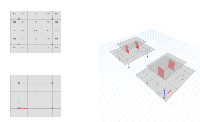
Let's say I have a tranfer slab which is gonna support the walls above. So I have modelled it in two different ways like below.
The first one is using multi shells around the columns below and walls above. The second one, on the other hand is one single shell with null lines (or dummy beams). Their meshes are the same.

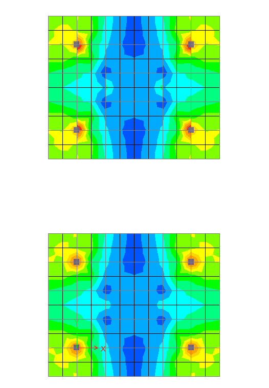
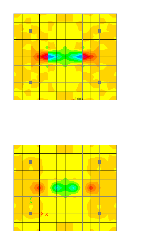
However, the stress looks different. The stress of the first method looks not right. I would like to know what seem to be problem for the first method?


Also, the wall above will become two point load applied in the slab in FEA instead line loads. Should we and can we do any amendment for wall objects and why?
Thank you.
I have a few questions regarding modelling in FEM software.
Let's say I have a tranfer slab which is gonna support the walls above. So I have modelled it in two different ways like below.
The first one is using multi shells around the columns below and walls above. The second one, on the other hand is one single shell with null lines (or dummy beams). Their meshes are the same.

However, the stress looks different. The stress of the first method looks not right. I would like to know what seem to be problem for the first method?


Also, the wall above will become two point load applied in the slab in FEA instead line loads. Should we and can we do any amendment for wall objects and why?
Thank you.
