Eng-Tips is the largest engineering community on the Internet

Intelligent Work Forums for Engineering Professionals

  • Congratulations waross on being selected by the Tek-Tips community for having the most helpful posts in the forums last week. Way to Go!

Transformed Shell Height and maximum length of un-stiffened shell 1

Status
Not open for further replies.

magmath

Mechanical
Mar 21, 2007
12
0
0
AU
Dear Experts,

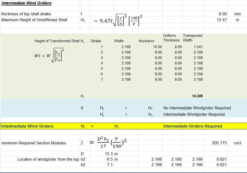
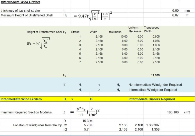
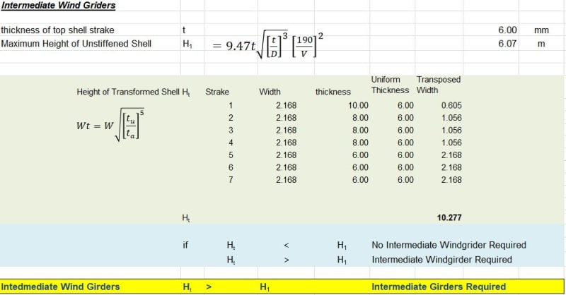
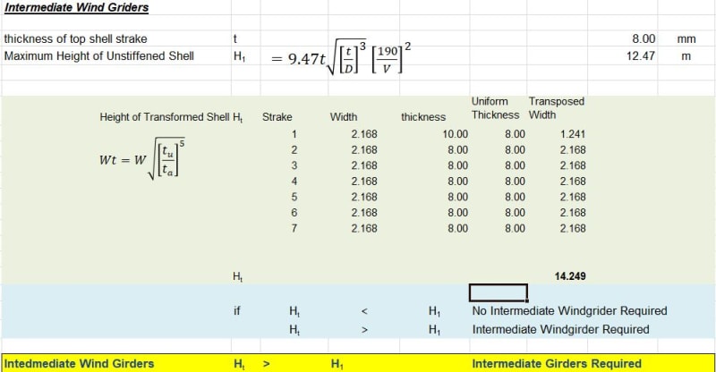
I am in the process of designing 15m diameter x 15m high tank. Calculated thickness for the top course is 2.7mm & the minimum requirement as per API650 is 6mm. However the construction team requested it to be 8mm so I have considered 8mm thick top course. Now the question is when calculating the maximum length of unstiffened shell and Transformed shell height for the design of intermediate wind girder which thickness I should use ie 6mm or 8mm?

Thanks in advance

Magesh
 
Replies continue below

Recommended for you

I have API 650 11th edition.

The transposed width is calculated with the formula given at 5.9.7.2
and Wtr =W*(SQRT(( Tuniform/Tactual )**5))

Definition of t uniform = as-built thickness, unless otherwise specified, of the thinnest shell course, mm (in.),
and tactual = as-built thickness, unless otherwise specified, of the shell course for which the transposed width is being calculated,
mm (in.).

The as built thickness will be understood as "as ordered" thickness that is, if corrosion allowance has been specified , it is the uncorroded thickness unless otherwise stated. That is, you may calculate the transposed width with tuniform= 8 mm.

Please also note that, if the top course 8 mm is chosen , the other courses shall not be less than 8 mm .
 
Thanks Hturkak,

when I calculate all these and finally calculate the section modulus of the intermediate girder required I am really confused as I need a bigger section of intermediate wind girder if I take 8mm as the thinnest shell thickness in comparison to 6mm thinner shell thickness. I have attached my calcs for easy reference...I thought it should be in the opposite way.

SectionModuluswith8mmShellTjick_nf4ffe.jpg
SectionModuluswith6mmShellThick_j3776i.jpg
 

By visual check, i think you used h2 ( in formula of Z ,required section modulus)...In your case H2 is 15 m.. (the definition of H2 = height of the tank shell (m), including any freeboard provided above the maximum filling height as a guide for a floating roof)

If you provide V = design wind speed (3-sec gust), i could check with a hand calculator..Notice that section modulus will not change for both cases..
 
V = 80m/s

I have used 5.9.7.6 to calculate the minimum required section modulus for the intermediate wind girder. I have positioned the intermediate wind girder as per 5.9.7.3.1 and hence h2 is different in both cases
 
While 5.9.7.3.1 is correct that you will have "equal" stability above and below by placing the wind girder (WG) at mid-span, it will not be the best location. My quickie numbers say the 8 mm shell would be good for about 105 m/s above and below a mid-height WG. You only need 80 m/s, so raise the WG until the permitted speed below the WG is 80 m/s.

In the case of your 8 mm shell this is (14.249 - 12.47) = 1.78 m below the top of ring 7.
In the case of your 6 mm shell this is (11.369 - 6.07) = 5.30 m below the top of ring 7.

The section modulus of the intermediate WG is proportional to the distance between it and the top of the shell (see formula for Z). Thus the 8 mm shell will require a section modulus that is (1.78 / 5.30) or only 34% of that required for the 6 mm shell.

One question for you. 80 m/s is 290 kph. Where is this tank going to be located?
 
Thanks Geoff,

It makes sense. Tank will be constructed in Fiji island and it is a cyclone area and the customer wants to design it to Category 5 cyclone.

When I further worked on the shell stability using Annex V for external pressure (for both wind & external pressure) I have used the below thickness (changed the thickness for the 4th ring from 6 to 8)

TransformedHeight6mm_itff1d.jpg

ShellStability_qrymdh.jpg


Using tank stability analysis of Annex V, I have arrived at the minimum shell thickness to resist buckling due to external wind pressure as 7.68mm. Now if I changed the minimum thickness to 8mm, I no need any intermediate WG as the tank shell itself can resist the external wind pressure. Is that right?

But re-calculating the requirement of WG using 8mm thick plate as per below, I still need intermediate WG...So I am not sure what mistake I am doing..
TransformedHeight8mm_lbagkf.jpg
 

V = 80m/s

I have used 5.9.7.6 to calculate the minimum required section modulus for the intermediate wind girder. I have positioned the intermediate wind girder as per 5.9.7.3.1 and hence h2 is different in both cases
.

I looked to both cases again.. For the thick. 8 mm top course , H1 =12.47 and Ht (equivalent transposed H) =14.25

H1< Ht but H1<Ht<2*H1 so you need one secondary wind girder..

and for 6 mm thk H1=6.07 mm , and Ht (equivalent transposed H) =11.39

H1< Ht but H1 is almost equal to 2*H1=11.39 so the use of two secondary wind girder should be questioned.

If you choose the first option, using the formula 5.9.7.6 , you can determine the required section modulus . The selected H1 ( vertical distance (m), between the intermediate wind girder and the top angle of the shell or the top wind girder )
H1 shall satisfy > (15-12.47) = 2.5 you may prefer H1 =4.0m

pls note that ,the secondary wind girder shall be located on shell courses having the same thickness with the top course.

You did not mention about the internal pressure..i will suggest you to look app. V , worked example .
 
Thanks HTURKAK,

I had a close look at the worked example is Annex V. I have external pressure due to wind, internal pressure is only 0.25Kpa

Noted in the worked example, minimum shell thickness were increased to eliminate the intermediate WG and the tank is further strengthened to withstand the external pressure.

If we have a intermediate WG, can that be considered as strengthening rings as detailed in Annex V?

 
.... internal pressure is only 0.25Kpa ,Noted in the worked example, minimum shell thickness were increased to eliminate the intermediate WG and the tank is further strengthened to withstand the external pressure.

If we have a intermediate WG, can that be considered as strengthening rings as detailed in Annex V?

I just want to remind the vacuum pressure rather than positive internal pressure which you defined 0.25Kpa .

Intermediate WG is considered as strengthening ring provided that the requirements of app. V8.2 satisfied.

Good Luck.

P.S. Are you sure for the wind velocity 80 m/sec ?.
 
Status
Not open for further replies.
Back
Top