Eng-Tips is the largest engineering community on the Internet

Intelligent Work Forums for Engineering Professionals

Transformer 30/0.4kV unbalanced currents 2

Status
Not open for further replies.

LMSANZ

Electrical
Jun 26, 2017
16
0
0
DZ
Hi,

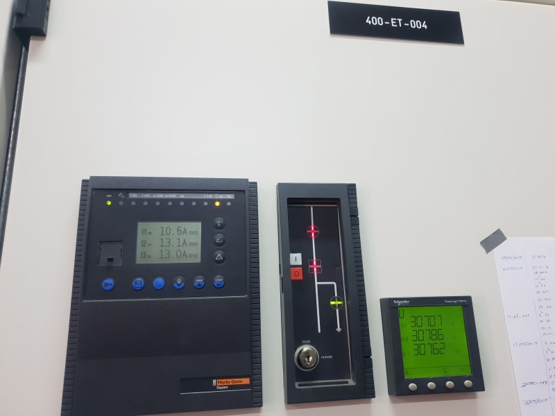
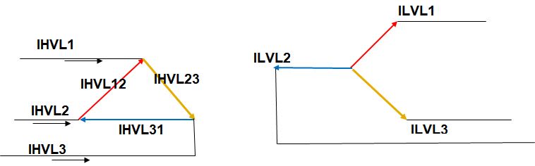
We have a distribution transformer 30/0.4kV 1.6MVA, which has the primary currents unbalanced. Secondary currents looks balanced +/- 80A. The transformer supply to MCC which has motor an single phase loads.

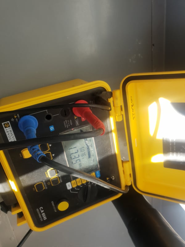
We've made insulation test 5000V 1 min, on primary side and the results are GOhms.
20190517_073845_chjdnr.jpg

20190517_073843_xim9wm.jpg

20190510_173407_o9ek9p.jpg

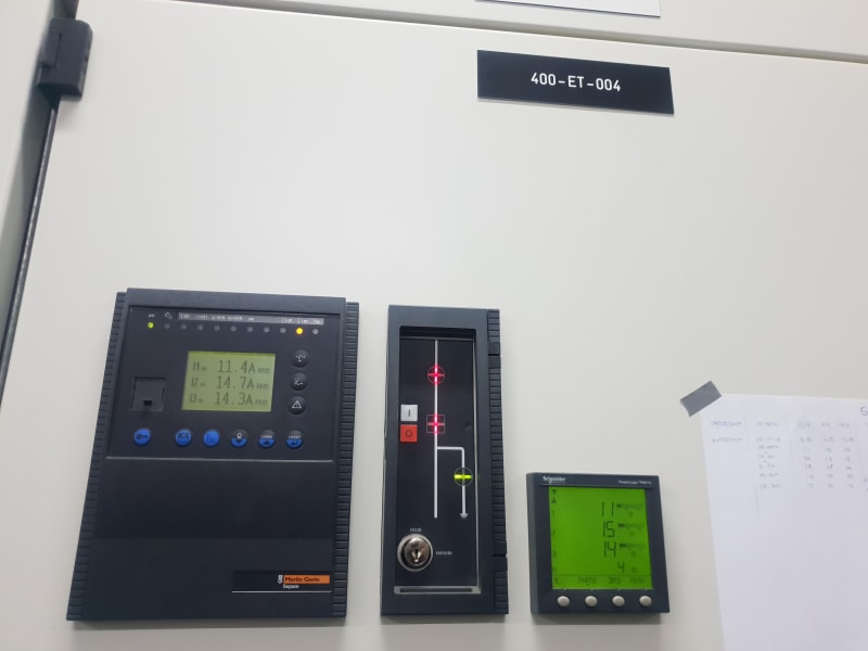
What can be the reason?

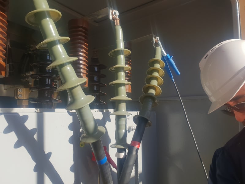
See attached picture.
Regards
 
Replies continue below

Recommended for you

Primary voltage looks balance. See Attached Picture.

Yesterday we've measured the secondary currents and we had: L1 1065A, L2 1015A, L3 1008A.

Transformer is 30kV Delta 400V Star, neutral solidly grounded.

20190519_135810_tacspw.jpg
 
I don´t think so.

The feeder has two sets of CT, one goes to protection relay SEPAM, and the other one goes to the Power meter. Both give us similar values for the unbalanced currents.

The unbalance seems to be around 2-3A, but when the demanded load increase the difference between phase L1 to the others increase to 3-4A.
 
What ratio are the primary CTs? If they're fairly high ratio (e.g., 200-1 or 200-5 are quite common) then a few amps difference between phases probably doesn't mean too much.

Cheers,
mgtrp
 
Well, the primary CTs are 50/1, they are Merlin Gerin type TCF4F/N2.

I think the secondary load is almost balance, only 6% unbalance between phase L1 and L3.

It seems that the unbalance current in primary side increases when the load increases, and decrease when the load decreases.

I am thinking about checking the ration and lineality of the CTs...
 
Well, we don't have the equipment at field. But we are going to check completely the 03 CTs of that panel:
- Insulation resistance test
- Ratio and Phase deviation test.
- Excitation (Saturation) Test
- Winding resistance Test
- Burden Test
- Polarity test


Hope the problem is at CT level. I don't know what else can be.
 
You could get this unbalance by having different phase angles on the secondary, even if the magnitudes were nearly balanced. This could come about be having some Ø-N loads and some Ø-Ø loads.

For example, with secondary currents of Ia = 1000A @ 0°, Ib = 1000A @ -100°, Ic = 1000A @ 120°, you would get IA = 11.79A @ 40°, 14.47A @ -80°, IC = 13.33A @ 150° in the primary. This assumes a 30/0.4 voltage ratio and no voltage drop.

You might be able to get phase angle measurements from either the relay or the panel meter.

[URL unfurl="true"]https://res.cloudinary.com/engineering-com/image/upload/v1558376829/tips/Mathcad_-_Dytran_uicwqh.pdf[/url]
 
"Balanced" 3-phase systems can exist in text books. You've said that you're feeding an unbalanced load on the low-side. Why are you seeing this as a problem to be solved?

Turn off the single phase loads, does the high-side become more balanced? Are the feeds to each of the 3-phase motors balanced? Does the high-side metering show any residual (3I0) current? If not, and turning off the single phase load reduces the imbalance, it just is what it is.

<edit>jghrist responded as I was typing
 
Thanks for the answers.

Well, the relay seems that start detecting I0 current from 4A, (10% of primary CT 50/1), because when the load increase the I0 start detection immediately from 4, and increases little by little acc to the demanded load. For example with primary currents L1=10.8, L2= 13.7, L3=13.2 the relay I0=0, but when the demande load increases to L1=11.5 L2=14.5 L3=14.0 the I0=4A. So far the maximum value we've got is L1=14.3, L2= 18.3 L3= 17.3, then I0=4.9A. The relay is a SEPAM T20, so quite basic model of SEPAM and it doesn't have the phasors monitoring when we connect the laptop.

@jghrist, thanks for the mathematical explanation, is absolutely perfect. Now the question is from where it could come this unbalance in phase angles of secondary currents?

 
You should have no I0 on the high side of a delta connected transformer. Maybe there is a CT error, but you say that the relay and the meter give similar readings from different CTs.
 
yes, it is a same physical CT but with two secondaries. Don't know if there is sth wrong with that CT.

In case there is a fault, it does make sense that the unbalance increase with the load?
 
HV_Unbalance_currents_h6kfhb.jpg

Like jghrist I calculated the HV current form LV-at first the transformer HV winding currents-and then the line currents. The windings ratio whv/wlv=30/(0.4/sqrt(3)=129.9.If we shall take the data from the post of 19 May 13:12 where the low voltage currents are mentioned and considering HV currents as per o.p. then the LV currents are-
L1 1065A, L2 1015A, L3 1008A.
considering L1 low voltage as 0 [reference]:
ILVL1=979.8-417.4i cosfi =0.92 [absolute 1065]
ILVL2=-926.6-414.4i cosfi=0.81 [absolute 1015]
ILVL3=372.4+936.7i cosfi=0.62 [absolute 1008]
Here is- indeed- a neutral current of 438.4 A [as sum of above currents].
Now, referring to HV and adding 0.34 A for each primary winding as no-load current[1.1% of rated] I calculated HV winding currents:
IHVL1L2=7.54-2.76i
IHVL2L3=-7.13-2.74i
IHVL3L1=2.87+7.66i
and now considering IHVL1=IHVL3L1-IHVL1L2
IHVL2=IHVL1L2-IHVL2L3
IHVL3=IHVL2L3-IHVL3L1 we get:
IHVL1=-4.68+10.42i and abs.value 11.42
IHVL2=14.68-0.023i and abs.value =14.67
IHVL3=-10-10.4i and abs.value=14.43
The sum of these currents is 0- as logic.
If we increase the current with 25%-keeping the cosfi constant- we get:
14.3;18.3;18 [close to data from 21 May 19:05 post.and Io[low voltage] will be 548 A
 
An anecdote to illustrate the effect of phase angles.
I was checking the currents in a residential panel, 15 Amp circuit breakers.
I checked two circuits with a common or shared neutral.
CCT #1, 9 Amps.
CCT #2, 11 Amps.
Shared neutral, easy, 11 - 9 = 2 Amps. NOT
The measured neutral current was 7 Amps.
But everyone knows that the neutral current is the difference between the two line currents.
The answer; Phase angles.
One load had a good PF and the other load had a very low PF.

The whole truth, which not everyone realizes is that the neutral current is the DIRECTED difference between the line currents.
Phase angle may matter more than you realize.

Is the PF of your motor loads high or low?
Is the PF of your single phase loads high or low?
You may be able to Guesstimate a quick answer to this question.
The answer may help to direct your efforts to more exactly locate the cause of the unbalance.

Bill
--------------------
"Why not the best?"
Jimmy Carter
 
Hi, I'm trying to get a power analyzer so we can check the phase angles of the secondary loads. We have another transformer feeding similar loads, and the overall PF is around 0.88.

I am also in contact with Schneider for checking the CTs so we can be sure that there is nothing wrong in the panel.

So, for the moment, nobody thinks that we could have sth weird inside the transformer?.

I am looking for a catalog for the CT.
 
Status
Not open for further replies.
Back
Top