Continue to Site

Eng-Tips is the largest engineering community on the Internet

Intelligent Work Forums for Engineering Professionals

  • Congratulations MintJulep on being selected by the Eng-Tips community for having the most helpful posts in the forums last week. Way to Go!

Transformer 30/0.4kV unbalanced currents 2

Status
Not open for further replies.

LMSANZ

Electrical
Jun 26, 2017
16
Hi,

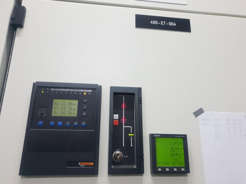
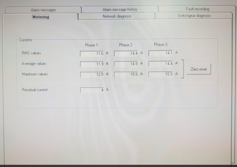
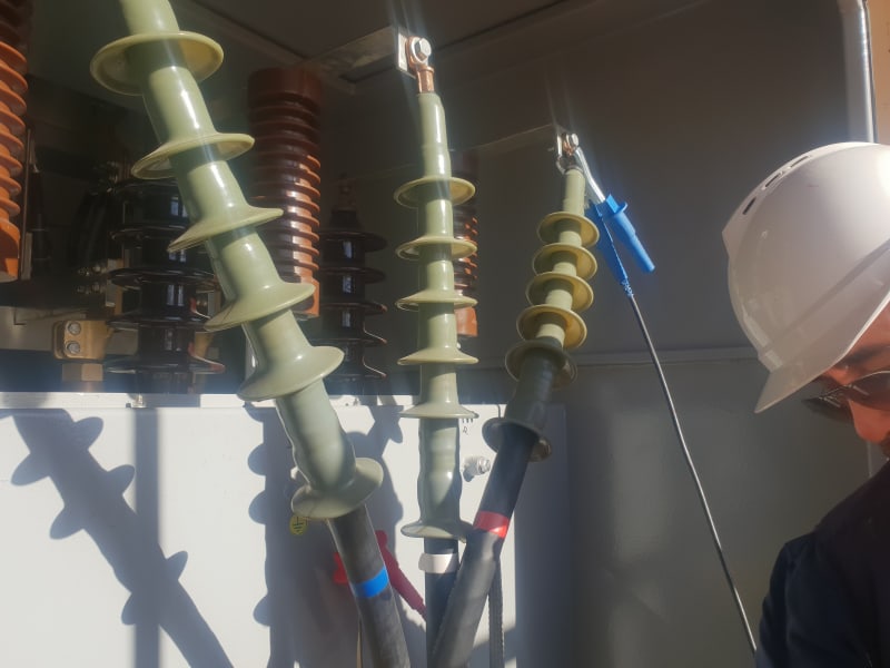
We have a distribution transformer 30/0.4kV 1.6MVA, which has the primary currents unbalanced. Secondary currents looks balanced +/- 80A. The transformer supply to MCC which has motor an single phase loads.

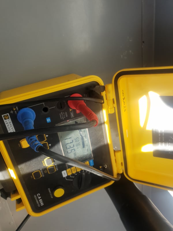
We've made insulation test 5000V 1 min, on primary side and the results are GOhms.
20190517_073845_chjdnr.jpg

20190517_073843_xim9wm.jpg

20190510_173407_o9ek9p.jpg

What can be the reason?

See attached picture.
Regards
 
Replies continue below

Recommended for you

I found this paper from IEEE, where it seems that the protection 51N can start detection false trips due to the unbalance currents. So it seems to me that 51N zero current calculations don't distinguish between ground fault or unbalance current?
 
 https://files.engineering.com/getfile.aspx?folder=ed796955-9664-422a-b1e6-8a10165d4d19&file=07102175.pdf
Relaying can't distinguish residual load caused by load imbalance or a fault. You have to make the distinction by setting the pickup so that it never operates under imbalanced load.

Zero sequence current can't pass through the delta on the high side so all of your residual current is going to be coming up the ground on the wye low side.

You are going to see negative sequence currents and voltages on the highside due to imbalance. Positive and negative sequence quantities will be sourced from the high side through the transformer to your load. With a mixture of positive and negative sequence, the phases will all add up to zero but the angles between the phases will no longer be 120 degrees.

------------------------------------------------------------------------------------------
If you can't explain it to a six year old, you don't understand it yourself.
 
Does the transformer have taps? A wrong tap setting on one phase may be the cause.
It's possible that one lead is on the wong tap.
A more remote possibility is that the taps were connected wrong at the factory.

Bill
--------------------
"Why not the best?"
Jimmy Carter
 
Well, the transformer has taps, +/- 2.5%, 5%, but the tap is common for the three phases.

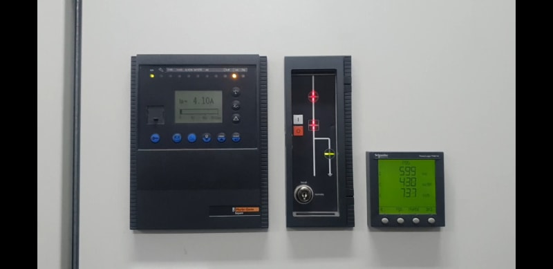
I understand that Zero sequence can't pass through delta winding, in the case of earth fault in secondary. But what happen if there is a starting fault in any of the primary windings of the transformer? Zero current will be present at primary line currents, at swgr level? . The relay is detecting residual current, but don't know if due to the unbalanced currents (bad CT in phase L1) or sth else.

20190524_193310_fjto0y.jpg


Screenshot_20190524-193212_Video_Player_qeil40.jpg
 
@7anoter4 In your calculation, whv/wlv=30/(0.4/sqrt(3)=129.9, but I would say it is rather whv/wlv=30/0.4=75 since, to my knowledge, the ratios of the transformers always are given referring to line-to-line values.
 
The voltage on each of the wye connected secondary windings is 1/1.73 of line to line voltage.

Bill
--------------------
"Why not the best?"
Jimmy Carter
 
Status
Not open for further replies.

Part and Inventory Search

Sponsor