Continue to Site

Eng-Tips is the largest engineering community on the Internet

Intelligent Work Forums for Engineering Professionals

  • Congratulations KootK on being selected by the Eng-Tips community for having the most helpful posts in the forums last week. Way to Go!

Transformer Current Distribution 1

Status
Not open for further replies.

Cerkit

Electrical
Jan 18, 2016
99
Hi,

I am looking at a star-delta (HV/LV) transformer configuration.

Please can you correct me if wrong on the following:

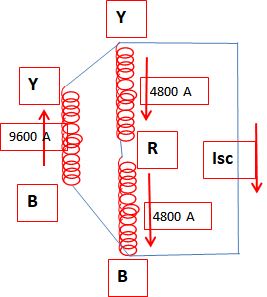
For a phase-phase fault external to the transformer on the LV side (delta side) with the source being on the HV side, the current distribution in the windings should be as I have drawn attached.

Thanks
 
 https://files.engineering.com/getfile.aspx?folder=0763fc20-bd2b-4a42-bee4-9330721fb569&file=Star-Delta_Ph-Ph_Fault.PNG
Replies continue below

Recommended for you

Not quite.
Consider this as a three transformer bank.
Remove the "Y" phase transformer.
"R" and "B" phase transformers will now act as an open delta.
Connect the fault across the open delta.
The fault current will be the same as the fault current through the "Y" phase transformer standing as a single phase transformer.
When a single phase fault is applied to a wye:delta bank, equal current will flow in all windings.
This is dependent on a connected primary neutral and on the supply connections being robust enough to maintain full terminal voltage on all phases with no neutral shift.
Voltage drops on the primary conductors will skew the currents somewhat.
For a single phase load applied to a delta transformer bank, "Y" phase will carry 50% of the load and "A" and "B" phases will each carry 25% of the load.
The KVA will be 150% of the kW.
Each transformer will carry 1/3 of the KVA.
When a three phase transformer bank is used to supply a single phase load, the bank loses at least 1/3 of the three phase capacity.
A single phase load may be supplied by abandoning one phase, with a zig-zag connection, with a double delta connection, with a star-diamond or Collin connection or by connecting across one side of a delta connection.

Bill
--------------------
"Why not the best?"
Jimmy Carter
 
In my opinion if =1600A and →→
Star_Delta_short_circuit_hvad1t.jpg
=3200 A it is correct.
 
Absolute values depend on transformation ratio. If U_RY_HV = U_RY_LV then I_R_HV = 1600*sqrt(3), I_Y_HV = 3200*sqrt(3)
 
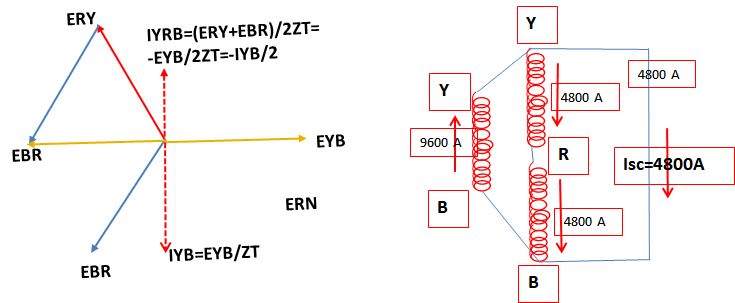
Sorry. My mistake: EYB=-(ERY+EBR) that means the currents are opposite.
So Isc=9600-4800=4800A
Delta_transformer_short_circuit_ymex32.jpg

Star_Delta_short_circuit_tlvrnz.jpg
 
Second picture is wrong. The algebraic sum of currents meeting at a point is NOT zero. You should reverse 4800 currents. But in this case zero sequence doesen't equal to zero. So first picture is the best IMHO. Zero sequence is zero. The algebraic sum of currents meeting at a point is zero too.
 
You're right AndreyIli. The arrow sense is wrong. But it will take more time for me to mend the picture.[lol]

 
7anoter4;
Take a look at your drawing of 4 Apr 19 14:47
The diagram implies that the primary neutral is connected.
The full diagram posted by Cerkit on 5 Apr 19 15:19 shows the the neutral is in fact grounded.
You show Y-R and R-B in a straight line.
However R phase forces a 120 degree voltage displacement.
Winding Y-R has the same EMF driving the current as winding B-Y and the winding has the same impedance as B-Y. The current will be the same as in winding B-Y.
Similarly the winding R-B will have the same EMF, the same impedance and the same current as winding B-Y.
While the total impedance of the windings is double, the driving EMF is also double, due to the phase displacement of the voltages.
Do a vector sketch of the voltage drops under load and compare with the voltage drop of the single winding with the fault.
As for the arrows, the direction of the currents is to add the current through the fault. (But you already know that.)
Also, in the case of a single phase load, the kW distribution is 50%, 25% and 25%.
However as a result of the phase displacements of the Y-R winding and the R-B winding, The KVA distribution is 50%, 50% and 50% of load KVA.
KVA will be 150% of kW.

Bill
--------------------
"Why not the best?"
Jimmy Carter
 
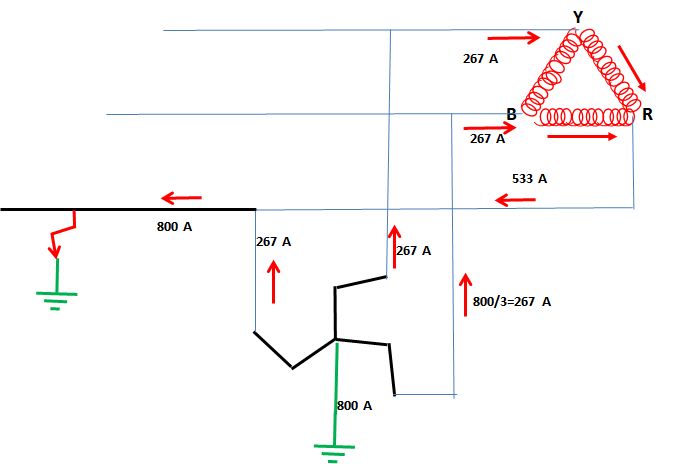
In my opinion if E.T. it is a Zig-zag transformer then the current distribution will be as in attached sketch.
I have to think more about your detailed interesting explanation, Bill , but it will require more time.
However, thank you for your remarks.
Zig-zag_transformer_ground_vwzl5v.jpg
 
The original question was in regards to a line to line fault so the zig-zag does not have an effect.
Let me explain a different way.
Consider a 100 Amp load on a single 120 Volt transformer. We will state that the voltage drop is 3 Volts.
Now consider the same load connected across an open delta. The same 100 Amps flows through each of the two transformers and each transformer has a 3 Volt voltage drop.
Now each transformer is developing 120 Volts but because of the 120 degree phase angle, the resultant voltage is still 120 Volts.
In a similar manner, the individual voltage drops are 120 degrees displaced so the resulting voltage drop across the open delta is 3 Volts.
Transformers with the same voltage drop under load will share the current equally.
When the virtual transformer formed by the open delta is put in parallel with the real transformer, the current is shared equally.

Another proof of the current sharing when a single phase load is connected to one side of a delta is found in the double-delta connection used to convert a three phase generator to single phase.
All the windings in the double delta carry equal current.
There is no de-rating of the current when the double delta is used.


Bill
--------------------
"Why not the best?"
Jimmy Carter
 
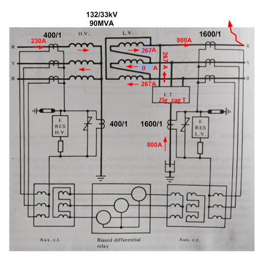
I am sorry. In my post of 6 Apr 19 19:50 I referred to the Cerkit post of 5 Apr 19 15:19 in which it is about phase R to ground.
Delta_transformer_R_grounded_icohhw.jpg
 
On the 132 kV windings the current [I hope the transformer it is at no-load !] has to be 267/4=66.75A only, of course.[blush]
 
OK.
However in your posts of 6 April 19 19:50 and 7 April 19 10:59 you appear to be neglecting the current on "R" phase.
That is correct for a floating wye point but not for a grounded wye point.
My comments are in relation to a grounded wye-delta.
Rather than a zig-zag I prefer a star-delta grounding transformer.
A star-delta may be constructed with "off the shelf" transformers, A zig-zag may be a special order.
In the event of a failure, a replacement may be on hand if the owner is a utility, and will be readily available from suppliers if the owner is a private concern.
The only time I had a possible use for a zig-zag transformer, I was so far out in the third world that the supplier's sales persons had no idea what a zig-zag transformer was and I had to use an alternate solution.
And personally, I find the star-delta solution easier to analyze.
Also, the last time I saw a zig-zag transformer installed was about 50 years ago.
I have over 15 years of experience dealing with the unique issues of the grounded wye-delta connection and no experience with a zig-zag.
Note: If we consider the to be a grounded wye-delta, then the situation is a ground on the primary of the wye-delta.
The only time that there is no current in one phase is when two primary phases are missing. (Single phase switching with fused cut-outs. This kills refrigerators and freezers. I've seen it many times. This was one of the issues of the wye-delta connection. I installed a lot of combination voltage monitor-time delay circuits on residential refrigeration and A/Cs)


Bill
--------------------
"Why not the best?"
Jimmy Carter
 
When I retired everybody told me that I'll have much free time. It's totally wrong. I now have much less free time. Any work requiring more time is delayed or is not doing. I have a list of 40 things urgent postponed.
I am very sorry but I can't answer for now, although I find it very interesting discussion.

 
Thanks everyone for your input. I always thought that I should be able to figure out current flows in a transformer for any fault by following a few rules but it's always a struggle. Hopefully I'll wrap my head around it. Thanks
 
Hi,

I am looking further into the fault current transformation. Please see attached from a book I am looking at. Please can you advise why do they show that there is current in all three phase on the 132kV side, when I modeled this scenario in a power system tool it is showing there is no current flowing in the R phase on the HV side for a B-Y fault on the LV side. Not sure what I am doing wrong...?

Thanks
 
 https://files.engineering.com/getfile.aspx?folder=466f1ac0-29ed-4325-8223-5e8e1b847c5d&file=IMG_20190412_154546.jpg
Maybe I'm wrong.
But try this.
Model an open delta with a load across the open side.
Model an open delta with a fault across the open side.
With a load, you will find current through all three phases.
I can't see it being different for a fault, but my experience with this connection has been with loading.
A single phase load in a generator causes equal current in all three delta windings.

Bill
--------------------
"Why not the best?"
Jimmy Carter
 
Status
Not open for further replies.

Part and Inventory Search

Sponsor