Continue to Site

Eng-Tips is the largest engineering community on the Internet

Intelligent Work Forums for Engineering Professionals

  • Congratulations KootK on being selected by the Eng-Tips community for having the most helpful posts in the forums last week. Way to Go!

Transformer tries to maintain flux a constant, then why does it still 'Saturate'? 1

Status
Not open for further replies.

Soloten

Electrical
May 29, 2018
14
My understanding is that at no load, a transformer does have a certain no-load flux in the core, due to the magnetizing current in the branch. When it is loaded, the secondary draws more current, create an opposing flux (Lenz's law) that opposes the primary flux - and this inturn reduces the self induced emf drawing more current from primary. So overall, in this process, the secondary flux and primary flux cancel out, and the flux still remains close to its open-circuit flux.

So my question is: What causes the transformer to saturate then? If primary voltage is increased, the load in the secondary will draw more current and should cancel out the primary flux and keep the flux in the core a constant right?

 
Replies continue below

Recommended for you

Saturation has little or no relationship to the load.
The flux is relatively constant at any primary voltage leve.
However, when the voltage is too high, further increases in current are no longer limited by the inductive reactance and the current increase is now limited mostly by the AC effective resistance of the primary winding.
Flux increase with an increase in applied voltage.
At 150% or 200% of rated primary voltage the flux will be constant at some level for a short time until the transformer burns up.


Bill
--------------------
"Why not the best?"
Jimmy Carter
 
When the primary voltage goes up, the flux in the core goes up. Secondary voltage also goes up due to this extra core flux. Depending on the nature of load, current may go up or down and flux due to the extra current will be nullified by the primary extra current. But the flux in the core due to the applied voltage will remain same. In fact this flux in the core is a function of applied V/f ie voltage /frequency.
 
There is "conventional theory", where things like saturation and hysterisis losses are neglected. And then, there are physical properties of the core material. Things like pemeability, saturation, hysterisis losses and eddy current losses.

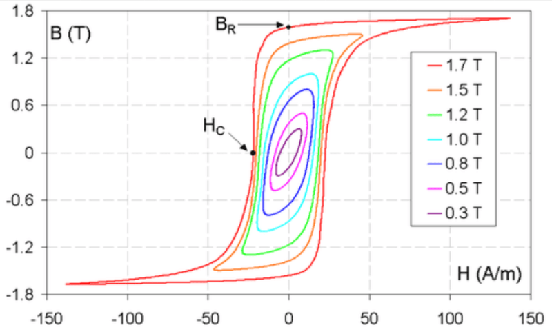
Saturation is seen between 1.0 and 1.5 tesla for most Fe qualities. Data are given in text-books and transformer plate manufacturer's data.

For ferrites, the saturation is much lower, high-frequency materials can have saturation as low as 300 mT and seldom go beyond 600 mT.

Then, there are amorphous metals, Alloys where thin (around 50 microns) sheets are cooled so rapidly that conventional crystallization doesn't "have time to take Place". Those materials can have saturation Close to 2 T. And, by heat treating it, nanocrystalline sheets are formed, which are used in special applications, like CM filters and measurement applications.

To sum it up; reality is a Little more complex than described by conventional theory. And, in Nature, Reality is what counts.

Hystereskurva_magnetiseringskurva_generell_1_btvcnj.png


Gunnar Englund
--------------------------------------
Half full - Half empty? I don't mind. It's what in it that counts.
 
Yes, but saturation, i.e. deformation of the current sets in already at the "knee". So saturation starts already at around 1.6 T and if you run at that flux density, there is not much margin to cover normal mains voltage saturation, which is allowed to be +/- 10% in EU, and probably about the same in CA.

Gunnar Englund
--------------------------------------
Half full - Half empty? I don't mind. It's what in it that counts.
 
Read "voltage variation" - not "voltage saturation".

Gunnar Englund
--------------------------------------
Half full - Half empty? I don't mind. It's what in it that counts.
 
Gunnar, with modern CRGO, transformer engineers consider 1.72 T as normal working flux density and the same is suitable to work at 1.9 T continuously during the 10 % system overvoltage conditions. Saturation set in at around 2 T, above which the flux overflows from core filling the gap between winding and core.
 
CRGO = Cold Rolled Grain Oriented?

Good to know. I thought the limits were somewhat lower. But it was a long time ago that I worked at ABB transformer works in Ludvika. The Tata Steel works in Surahammar are testing a new thing, they call it HiLite and it has interesting properties. Available down to 100 microns (4 mils). Good for higher frequencies.

Gunnar Englund
--------------------------------------
Half full - Half empty? I don't mind. It's what in it that counts.
 
Gunnar, looking at the B-H curve you posted, I can see that an increase in current (H) causes some saturation (flat B), but I'm still wondering how the transformer behavior would allow this? Because an increase in secondary current should increase the primary current; The additional fluxes caused by primary and secondary should cancel out - and this should leave a constant flux density in the core. But it definitely isn't a constant flux density as seen in the BH curve. Can you help me clear out where I'm going wrong here?
 
The flattening B-H curve means that B (flux density) doesn't follow input linearly. The conventional theory assumes that the B-H curve is a straight line (no saturation, no eddy current losses and no hysterisis).

So, when you try to apply conventional theory to a transformer that doesn't behave like the conventional theory says it should - you cannot use the conventional (or idealized) theory. It is not anything new or mysterious with that.

A rubber band has the same problem - theory says that length increases linearly with force and force is removed, it should return to original length. It doesnt. It is very easy to demonstrate. Pre-stress a band by hanging a light weight in it. Then add a Heavy weight and see length increase. Double the weight and see length increase more. Then remove the Weight and note that the band doesn't return to its first position. If you are very ambitious, you can do that for five or ten different loads and plot the curves up and back. That may give you a feel for it.

Gunnar Englund
--------------------------------------
Half full - Half empty? I don't mind. It's what in it that counts.
 
Gunnar, is that B-H curve test done on a transformer with secondary open and by applying increasing voltage from the primary to increase the current? If so, would the self-induced Primary voltage be close to the supply voltage before saturation, but collapse after saturation? -- And just to make sure: The Self-induced primary voltage with the formula E = 4.44f(phi)N cannot be measured in across the terminals right, considering this is a 'self-induced back-emf, sort of? Would having a load connected in the secondary change things?
I hope I'm not complicating things
 
You are complicating things. If you want to understand, you should do some "research" on your own. Why do you think that the primary voltage cannot be measured? It can. Absolutely. No doubt about it.
There may be some secondary* effects like IR drop in the winding but that is not at all important for what you are struggling to grasp. In an idling Winding you probably have a lot less than one percent influence from IR drop. You can safely ignore that.

*Not transformer secondary - I hope that is clear.

Gunnar Englund
--------------------------------------
Half full - Half empty? I don't mind. It's what in it that counts.
 
Okay, thank you, that clears the primary voltage part, but what I was getting at was if you are saying that the transformer 'does' saturate for increasing current (based on my question) because of non-ideal conditions, my question is this:

1. Shouldn't the primary voltage increase to a high value that the V/f limit causes saturation? I can see that happening in a B-H curve experiment where the H increase can itself be achieved by increasing the V in the experiment, but how is this phenomenon happening in the real-world for a power transformer -- would you say this could be more likely due to primary voltage increases than overloads or secondary side faults?

2. If not, and if you consider an example of a secondary side short circuit fault, and say that it could cause the power transformer to saturate, would you be kind enough to step me through the cause-effect leading to it - Like the secondary current increases, primary current does too, but beyond that would the voltage/hz change enough to saturate, since the voltage would more likely dip during that fault -- what is the missing piece here?

I'm sorry I am beating this to death, but I did do a lot of research (probably too many sources causing this 'saturation' in my brain) and everything just seems muddled up at this moment. Hopefully, I and some others could benefit from reading this. Thank you for all your answers.
 
The secondary current does NOT have much to do with saturation. It is all about the total volt-second area that a certain transformer core can accept Before getting into saturation.

There is something in you notion of flux and voltage that you refuse to understand. Go back to a basic text-book and read about a single Winding core. Forget completely about any secondary current. I Think that is what makes you confused.

A side note: Many smart and intelligent guys are used to understand things without thinking much about it. I get the impression that you are one of those. You are not dumb? Are you?

It needs some thinking. As most other things in your life.

I am, as you probably have noted, very near my limits now.


Gunnar Englund
--------------------------------------
Half full - Half empty? I don't mind. It's what in it that counts.
 
Okay, I get where the confusion arose now. Thank you for your answer and for being patient with me.
 
Thanks, I hope it helped.

Gunnar Englund
--------------------------------------
Half full - Half empty? I don't mind. It's what in it that counts.
 
Waross,

Transformers saturation is impacted by load. The amount of iron in the core is dictated by low load requirements. Most transformers have as little core as needed. I have heard of deltas being used to provide a path for third harmonics generated by unloaded transformers.

------------------------------------------------------------------------------------------
If you can't explain it to a six year old, you don't understand it yourself.
 
HH
Please, do not obscure and confuse where it isn't necesssary.

The third harmonic is a result of the overvoltage that a lightly loaded transformer sees (and is designed to handle). Of course, the line voltage in a distribution system is (slightly) dependent on line current. But that is not a property of the transformer itself. Please, let the OP grasp the fundamental concept Before you tip him over with things that are system effects more than component properties. We do not want that frequency discussion again.

That you "have Heard" about something doesn't mean that we all are unknowing. If you work with Power syatems and drive systems, you not only "hear about", you actually can hear the harmonics as such. And see them. But all that is an entirely different discussion.

Gunnar Englund
--------------------------------------
Half full - Half empty? I don't mind. It's what in it that counts.
 
Status
Not open for further replies.

Part and Inventory Search

Sponsor