Continue to Site

Eng-Tips is the largest engineering community on the Internet

Intelligent Work Forums for Engineering Professionals

  • Congratulations waross on being selected by the Eng-Tips community for having the most helpful posts in the forums last week. Way to Go!

Transformer [Unbalanced loading concepts] 1

Status
Not open for further replies.

AAffoonnjjee

Electrical
Apr 10, 2017
16
Good Day,

My question is in regards to connecting an unbalanced load, single phase, 120VAC (10 fans) to a delta-delta transformer. Load is 8.3A rated current at 120VAC. Once we connect these 10 fans to the transformer we have phases B and C broken. Why is it that there will be a virtual and a real transformer? Which phases are the virtual, is it the one to which we connect the load, or is the ones that are broken? Now, if our pf = 1 (purely resistive load) and we have a 10kW load, the A phase supplying power to the load will split into 5KW and 5KVA. Why does it split? Where does the 5KVA comes from? Similarly, the other two phases (B and C) provide 5KVA each. I’m confused about why that occurs. Could someone clearly explain this topic with diagrams and point to a text where it explains this notion. Please help explain/visualize this. Also, if we have a center-tapped delta-delta transformer and we tie 10 fans between two phases and neutral, would we also have this virtual transformer issue?
 
Replies continue below

Recommended for you

Experts, could someone answer my question. I would very appreciate it.
 
The question makes no sense. What do you mean “broken” and “virtual”? How do you expect fans to have a PF of 1?
 
davidbeach,

First of all, I used pf = 1 as an example. Let's say that our three phase delta-delta transformer has Phases B and C unloaded and only phase A is connected to the 10 fans. That way, we connect the 120VAC, single phase fans between Line A and ground while the other two phases are open or broken. I am referring to an example from a thread I found on this forum (link below), the only drawback is I do not understand waross's explanation. In that thread, he also used the term 'virtual transformer' and I took it from him. If someone can actually explain in simple English what is meant by his answer I would appreciate it.

waross 23 April, 02:37
 
There are closed delta transformers and transformer banks and open delta transformer banks.
An open delta connection in North America develops three phase power with only two transformers.
The two real transformers together form a virtual transformer in place of the missing third transformer.
You are mixing the two systems up. No wonder that you are confused.
However, for the purpose of single phase loading on a delta transformer bank it sometimes helps to consider a single phase transformer in parallel with the virtual transformer formed by the open delta.
Consider a single phase transformer on "A" phase.
Now consider "B" and "C" phase transformers forming an open delta virtual transformer.
Lets call this virtual transformer A'
The characteristics of the virtual transformer, A' are similar to the real transformer on "A" phase which we will call A.
So for single phase loading on a delta transformer we can consider two similar transformers in parallel.
The "A" phase transformer will take 1/2 of the load, that is 5 kW.
The virtual transformer will take 1/2 of the load but the virtual transformer is comprised of two transformers so each of the "B" and "C" phase transformers will supply 1/2 of 5 kW or 2.5 kW each.
The KVA splitting is a little more interesting.
The same current flows through all three transformers.
The KVA on the A transformer is simply 1/2 of the load KVA.
But, the current through the "B" phase and the "C" phase will be in phase with the current in "A" phase.
That results in the other two transformers running at a power factor of 50%.
2.5 kW at a PF of 50% gives a KVA of 5 kW.
So a single phase load on a three phase delta bank will have transformer KVA of 150% of the load KVA.


Bill
--------------------
"Why not the best?"
Jimmy Carter
 
Let me try that a different way:
A 5 kW load on a single phase transformer will draw 5 kW and 5 KVA.
A 5 kW load on the virtual transformer formed by an open delta will draw 5 kW and 10 KVA, due to the phase angles of the current.
Now if we put the real transformer and its load in parallel with the virtual transformer and its load we can add the kWs and the KVAs.
We gat 10 kW and 15 KVA.
I hope that this helps.

Bill
--------------------
"Why not the best?"
Jimmy Carter
 
Hi waross,
Thank you a million for your response. With your explanation it became clearer to me.
In my understanding this only applies when we have removed one of the phase transformers from the delta-delta three phase transformer bank.
Another question I have is whether this virtual transformer and real transformer power splitting phenomena occur when we have a three phase delta-delta bank, center tapped, providing 120VAC single phase and 240VAC three phase on the secondary?

 
No don't remove a transformer.
The three phase delta, three transformer bank stays as it is. The example of the virtual transformer and the real transformers is to explain the loading. When you put the real transformer in parallel with the virtual transformer, you have the original three transformer delta bank.
Yes but the splitting is more complicated with 120 Volt loads.
Now part of the load is supplied directly by the 120 Volt winding. The transformer/phase that the load is connected to is still supported by the other two phases, but now the in phase transformer is also acting as an autotransformer.
I am not sure of the exact load splitting. I have never had occasion to work it out.
Are you following this thread ElectricPete?
Can you help us on this one?

Bill
--------------------
"Why not the best?"
Jimmy Carter
 
waross

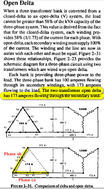
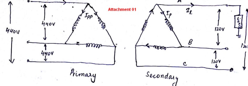
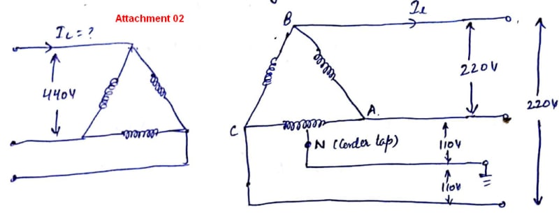
Now I'm a little confused again. In your earlier post you wrote: 'An open delta connection in North America develops three phase power with only two transformers. The two real transformers together form a virtual transformer in place of the missing third transformer.' I have been reading this text (excerpt below) about open delta. Could you confirm if what we both are talking about is part of the same concept. In the text they refer to open delta as a condition when one of the transformers, let's say ba, is missing or has been removed from the three phase transformer bank. Please explain what should be understood by this statement as well: 'However, for the purpose of single phase loading on a delta transformer bank it sometimes helps to consider a single phase transformer in parallel with the virtual transformer formed by the open delta.' Does this mean we have two transformers and we could connect single phase load in between either phase and ground; however, for calculation purposes of loading we need to imagine we have a virtual transformer (our phases ab and ca from text below) and a real transformer in parallel with each other? In other words, in one situation the schematic would look like attachment 01 and in another case it could look like attachment 02. What are the differences and similarities going back to this virtual and real transformer concept? Please lead me in the right direction.
2018-10-08_211322_ekeuri.jpg


2018-10-08_213155_rlzxyd.jpg


2018-10-08_213107_jzhsw7.jpg
 
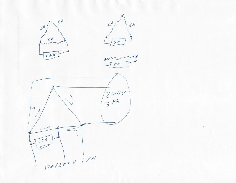
This shows a 10 Amp load on a delta transformer. Next shows how the load splits between the in phase winding and the out of phase windings.
1_zpcofb.jpg

The four wire delta connection is often used to feed both three phase loads and single phase loads.

Bill
--------------------
"Why not the best?"
Jimmy Carter
 
waross,

So, your four wire (A, B, C + Neutral) delta connection will also exhibit the virtual transformer and real transformer concept? For any single phase load we connect to a delta transformer we will always have this occurrence as long as the load is unbalanced? In other words, what are the requirements for a delta connected load and configuration (4-wire or 3-wire) in order for this concept to be true?
 
Yes. Concept is the important word.
When one transformer is removed fro a three transformer bank, a virtual transformer is formed in its place. That virtual transformer has similar %impedance(single phase), and voltage regulation as the transformer that it is replacing.
The virtual transformer may be considered as a single phase transformer in parallel with the appropriate phase transformer to explain load sharing and the increase in transformer KVA losses.
When a small three phase load is to be serviced in a residential area with mostly single phase services an open delta connection is often used.
Usually a customer will have one or two single phase motors or a large three phase A/C unit.
Typically there may be a fairly large single phase transformer serving a number of residential loads.
A smaller transformer may be added in open delta to provide a small amount of three phase power.
You may see a 5 KVA, or 10 KVA beside a 25 KVA, 50 KVA or even a 100 KVA transformer.
In the field the size difference is often readily apparent.
As long as the smaller transformer has a Full Load Current rating greater than the motor FLC the small transformer will carry the load safely.
However if a second small transformer is added to make a full delta bank, the sharing of the single phase loads may overload the smaller transformers.

Bill
--------------------
"Why not the best?"
Jimmy Carter
 
Status
Not open for further replies.

Part and Inventory Search

Sponsor