Eng-Tips is the largest engineering community on the Internet

Intelligent Work Forums for Engineering Professionals

  • Congratulations waross on being selected by the Tek-Tips community for having the most helpful posts in the forums last week. Way to Go!

Translators tolerances 1

Status
Not open for further replies.

javaxp

Automotive
Jul 14, 2014
43
0
0
ES
Hi,

I am suffering from annoying translating behavior.
I need to export several closed profiles for import in a "wiring cutting application".
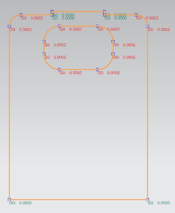
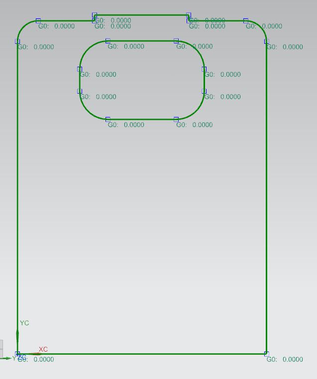
In NX, my curve profile is completely closed: I can to extrude, and the continuity G00 is perfect. If I export the profile in dxf, the "wiring cutting application" says that there is a GAP. Then if I import this dxf profile in NX, the profile now is opened (about 0,00014 mm.)!!
Is there a posibility to play with the tolerances to avoid this behavior?

Thanks in advance

Javier
 
Replies continue below

Recommended for you

Do any of your profiles make use of splines? If you are using the option to convert splines to polylines, there is a tolerance value in the dxfdwg.def file that you can adjust (looks like 0.08 mm is the default tolerance).

What modeling tolerances are you running in NX? For metric files, I think the default is 0.01mm; a 0.00014 mm gap should be considered coincident in this case. Unless you work with very small parts and have adjusted the modeling tolerances...

www.nxjournaling.com
 
Hi Cowski,

No, there is no splines, only lines and arcs. The modeling tolerance in NX is the default 0.01 mm. I´ve played with this tolerance but it seem to be unrelated.


Regards,

Javier
original_part_qmdwdn.jpg
after_translating_and_reread_in_NX_icpdpi.jpg
 
What occurs to me is that there is a limit to the accuracy of the floating point representation in the DXF file which is being exposed by the arcs - each arc has 5 dimensions: the X and Y location of the center, the R(adius), and the Start and End angles. They typically do not include the exact X and Y coordinates of the end points. So in that stack of dimensions to get each endpoint if the DXF file doesn't have enough digits to represent those values when it gets read back in they will be the truncated values.

What is interesting is that were they splines the endpoints are an explicit value and could be the exact same, potentially truncated value, as the line segments.

There's a paper called "What Every Computer Scientist Should Know About Floating-Point Arithmetic" (one version at ) which may help to understand why this may be the root of this problem.
 
Hi 3DDave,

I believe you are right in your reasoning, it matches the behavior observed.

A posible solution would be to export arcs as splines when translating to dxf, but I think this is not possible.

Anyway, Thanks for your response.

Regards,

Javier


Check if that application can use a different file format.
some years ago I had the same issue but with a software to cut labels / Stickers for the machinery we designed.

Regards,
Tomas

Never try to teach a pig to sing. I wastes your time and it annoys the pig.:)
 
What version of NX are you using? Also, what is the largest dimension of your profile (vertical dimension top to bottom)? I ran a quick test in NX 1992; I made a rectangle with rounded corners in a sketch and exported it to DXF. Importing this to a new file and the continuity was OK in both files. Maybe it has to do with DXF export/import options?

www.nxjournaling.com
 
Hi,

Toost, sadly tere is no other formats allowed on the application.

Cowsky, I'm runing NX 12.0.2.9 MP14, because our main customer is still on NX12. When I have the opportunity I will try another higher version. The profile's dimension is about 65 mm.

The translator options used are:
- Export Complete part​
- Export Selected View: "VISTA_CORTE"​
- LAYER SELECTED: 90​
- DXF Revision R12​
- Export spline as Spline​

3DDave, attached is a zip file with the original file (210863_2100_113.prt), the dxf exported file (MAGPLAN_20_210863_2100_113.dxf) and the "reloaded" file (MAGPLAN_20_210863_2100_113_dxf.prt).

Thanks to all

Regards,

Javier


 https://files.engineering.com/getfile.aspx?folder=2bd2740a-41b4-4ddc-87b1-207c8ee5730d&file=210863_2100_113.zip
I fired up NX12 (12.0.2.9, no patch) and did a trial. Here are the settings I used:
Export:
export to - DXF
Export as - 3D
other settings - as you listed above

Import (to NX, new mm file):
workflow - 3D
units - mm
default NX options for all others

Curve continuity reports G0: 0.0000 for all curve connections.

www.nxjournaling.com
 
Hi cowsky thanks for your support.

With the option Export 3D I also get correct continuity, but unfortunately we need the options Export 2D and Export Selected View: "VISTA_CORTE" because we design in context and there are a lot of parts whose geometry orientation do not match the Absolute Csys. The wire-cutting application only accepts closed profiles on X-Y Plane from Absolute Csys.

Regards,

Javier


Hi,

I've tried on NX1782 version and it performs OK. It looks like this is a bug and has nothing to do with tolerances or options...

Thanks to all.

NX 12.0.2.9 MP14
 
I have a work-around that will get what you want. However, it can be a bit more time-consuming. If you are going to be stuck on NX 12 for a while, I can write it up (if you are upgrading soon, the work-around won't be worth it).

www.nxjournaling.com
 
Javaxp
Are you using the 2D exchange translator and NOT the DXF/DWG Translator ?!?
If yes, I think I know where you get the gaps from.
The 2D Exchange will flatten whatever you are looking by doing a CGM export to a temporary file, create a temporary part file and import the CGM and finally export the temporary part into the selected output Iges/ DXF/DWG.
The intermediate CGM should be the reason for the gaps. The CGM format was designed to be fast and simple not ultra precise.

Regards,
Tomas


Never try to teach a pig to sing. I wastes your time and it annoys the pig.:)
 
Hi,

I've done some test with CGM as intermediary, and you both (Toost and cowsky) are right: using cgm eliminates the problem with the gaps, but is also true that the result is not accurate enough.
Another work-around would be to create an assembly with the piece, reposition the component to Absolute Csys, and extract the curves on the assembly file, then export as dxf...I will try tomorrow.

Regards,

Javier


NX 12.0.2.9 MP14
 
Hi cowsky,

Yes, it meets. I have tried with several parts and the continuity is OK and the deviation is totally acceptable. It's a bit laborious but it does the job.


Thanks. Once again I have found a solution in this forum.[bigsmile]

Regards,

Javier


NX 12.0.2.9 MP14
 
Status
Not open for further replies.
Back
Top