Eng-Tips is the largest engineering community on the Internet

Intelligent Work Forums for Engineering Professionals

Transmission system overvoltages during major load throw-offs 4

Status
Not open for further replies.

RRaghunath

Electrical
Aug 19, 2002
1,712
0
0
IN
Transmission systems face Over voltage issues during grid disturbances when there is loss of major loads, leaving a large no. of unloaded or lightly loaded lines in the system (with associated excess VARs).
How do utilities control the situation? Is tripping of identified transmission lines an option followed by any utilities and if so, is the tripping logic based on OV+<MW+>MVAR??
Appreciate sharing any experiences. Thanks
 
Replies continue below

Recommended for you

Why trip lines for over voltage? Trip capacitor banks, close reactors, or change transformer taps are other options.

Where large jumps in voltages are expected, SVC devices are typically installed.

Tripping unloaded lines is not a first option.
 
Sounds like tripping lines used to be quite common overnight for planned voltage control, but utilities within the western United States have shifted away from removing lines from service to control high voltage. Now for regular voltage control in overnight hours, some hydro units are run as syncronous condensors. Synchronus condensors have fairly high losses, so this practice may be more expensive than removing some of the 500 kV lines from service.

Our system can drop a very sizable chuck of load without extreme overvoltages. However, during a blackstart event, controlling for overvoltage is one the main regional contraints. During restoration dicussions, there is often a vigorous debate about the most reliable way to restore the system. Unfortunately, adding enough load to control high voltage also positions the system for overloads if a 500 kV trips back out.
 
Taking lines out of service is still done in the UK--the retirement of synchronous generation and the addition of large amounts of inverter-based embedded generation has made high voltages an issue. Certain circuits are designated for voltage control.

Another utility that I previously worked for effectively tripped lines after certain system events, as it was prone to some fairly extreme voltages due to the nature of the network. Tripping was done automatically via overvoltage trips on key transmission lines, with setpoints and time delays based on system studies for various contingencies. A potential improvement that we were looking at was to use MVAr flow to adjust the time delays in areas where it was difficult to determine exactly which circuit to trip, although this hadn't been implemented when I left.

Cheers,
mgtrp
 
Many could be following this route (tripping identified lines on overvoltage) to control overvoltage as it is simple. Wonder whether they use MW check to identify lightly loaded line or any other criteria??
Not sure how much relevant MVAR check will be??
 
Within my utility, selected capacitor tripping, placing of reactors in service, and SVC response are the only actions undertaken without operator intervention to combat excessive overvoltage; removal of HV ckts from service, although done often enough, is never a first option, and is only performed via operator control.

On a side note, and tangential to the topic of this thread...

An interesting wrinkle developed within my utility recently when removing a HV circuit from service for voltage control, viz., the ckt normally used for this purpose was upon this occasion not the preferred one due to a planned outage on another transmission ckt, so an alternate was chosen in its place. The alternate terminated within the switchyards adjacent to two generating stations, one of which had operating units while the other's units were idle. Upon removal of the remote "idle station" end of this circuit, a neutral overcurrent alarm was promptly received on one of the operating units at the local end of the circuit...

Turned out this problem had never been encountered before; its cause was eventually attributed to the resultant electrical characteristics of that exact consist of ckts due to the various lengths of line for which specific phases occupied specific positions on specific portions of the line before they were rolled. It was a bit of a head-scratcher there for a while; no actual fault ever occurred, so manual current traces collected in various configurations had to be gathered and comparatively analyzed to determine what was going on. At the time, however, the sudden and completely unexpected receipt of this alarm roused some panic in certain operators, and reportedly it took one of the cooler heads of a more experienced senior operator to dissuade the more panicked staff from precipitously forcing that operating unit from service...

CR

"As iron sharpens iron, so one person sharpens another." [Proverbs 27:17, NIV]
 
Thanks for sharing your experiences CR.
The neutral Overcurrent alarm was due to lack of transposition in the OHL conductors.
I have seen currents in three phases not being identiaal in magnitude where the line is not transposed.
 
PJM sometimes mishaps transformed to circulate cars and bring the voltages lower during low loading condition. They have a paper on it. I suppose the cons of it would be that you are heating up the transformer, losing capacity, and moving taps.

------------------------------------------------------------------------------------------
If you can't explain it to a six year old, you don't understand it yourself.
 
As a consequence of the increase of distributed generation from renewable energy sources, the reactive power regulating resources sharply dropped in Italy.
We installed more than 8000 Mvar of EHV variable shunt reactors (mainly 420 kV class - 285 Mvar units) in order to cope with high voltages at low load or when the renewable energy sources are providing a significant share of the load demand.

Variable shunt reactor are a fairly cheap solution, with extremely low losses (about 0.15%). Although their variation range is limited, about 30% of the rated power, they are a far better solution if compared to disconnecting HV and EHV transmission lines.


Si duri puer ingeni videtur,
preconem facias vel architectum.
 
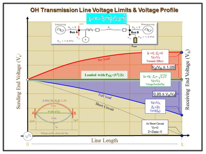
During a light loading condition, an overvoltage could happen at the receiving end of the line due to the Ferranti effect associated with the line distributed capacitance.
Since the equipment including insulators, circuit breakers and electrical apparatus typically are designed to operate up to 1.05 pu above the nominal system voltage, this value must be guaranty to maintain the system integrity.
There are a few options to keep the overvoltage under control. However, one of the most popular voltage regulation strategy is using shunt reactor compensation during light loading conditions. See the sketch below used as an Illustration of the possible voltage profile along an OH T. Line.
OH_T_Line_Voltage_Profile_t3rt5z.jpg
 
Status
Not open for further replies.
Back
Top