Eng-Tips is the largest engineering community on the Internet

Intelligent Work Forums for Engineering Professionals

Tripping Circuit - Blocking Diode Characteristics 1

Status
Not open for further replies.

Distribution73

Electrical
Mar 18, 2015
39
0
0
ES
Hi,
I would appreciate it very much to know your opinions on the following subject:
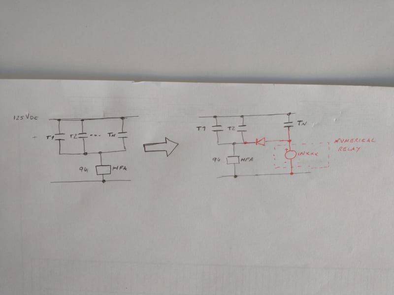
We are modifying an existing electromechanical busbar tripping circuit, and we would like to segregate the new trip contacts by means of a blocking diode. The control voltage is 125Vdc.
The new tripping branch we are including is intended to energize existing GE-HFA type relays which in turn trip a number of busbar breakers. It doesnt energize the trip coil of a breaker itself.
For this type of application, I have been advised to use a 30A forward current, 1200V PIV (reverse voltage)diode.
My queries:
- Do we really have voltage peaks any close to 1200V when we switch currents of tripping relays? I have come across products from GE (102L218G8) or ABB (TRB-2) that appear to to be intended for this application and they are rated for lower voltages (600V/200V respectively).
- Is there any P/N which is typically used for this application? I have seen ST diodes or Semikron that appear to be suitable, but not sure if there is any particular easy to find p/n.
- Any other particularity/characteristic that should be considered for this type of application?
Thank you very much in advance!
 
Replies continue below

Recommended for you

It appears you are concerned about surges on your DC bus.

Have you looked at what is called "free-wheeling" diodes on your coils? Maybe surge capacitors?
 
Inductive kick:
An energized induction coil stores energy in the magnetic field.
When the current through the induction coil is interrupted, the magnetic field collapses and induces a back EMF.
Whatever current was flowing tends to keep flowing.
The voltage across the coil is determined by the formula E=IR.
E = The inductive "kick" voltage.
I = The current through the coil.
R = The resistance of the coil plus the resistance of the arc across the breaking contacts.
If the current is interrupted instantly, the resistance across the contacts approaches infinity and the voltage across the coil approaches infinity.
In practice, the resistance of interest and the resulting voltage are limited by contact arcing and/or insulation breakdown.
In your case, the "kick' voltage will be determined by the characteristics of the coil in the relay and the arcing characteristics of the contact interrupting the circuit.
Consider a freewheeling diode or a suppression circuit across the relay input.
I still remember an experiment in high school physics.
A small, simple buzzer was energized by 6 Volts. A small neon lamp that required about 70 Volts to light was connected across the buzzer coil. The inductive kick was enough to light the neon lamp. That is greater than 70 Volts from a 6 Volt source. A ratio of over 10:1
This is one instance. Results will vary widely depending on the characteristics of the induction coil (relay coil) and the breaking contacts.

--------------------
Ohm's law
Not just a good idea;
It's the LAW!
 
Thank you very much cranky108 and waross for the great feedback.
What we are trying to achieve in our case is to segregate a trip branch so that we can monitor it.
I think the sketch will clarify more than my words:


IMG_20211012_121029673_mucmeh.jpg

What we are trying to do is to "Monitor" the operation of Tripping Contact "N" (using a numerical IED input), which is connected in parallel with a number of other tripping contacts.
I suppose the rating of the diode will have to do much with the inductive kick and surges you were mentioning but
its purpose being to isolate our branch from them not directly to control or reduce them.
In your experience, should we go for a >1000V reverse voltage diode? Is there any type or manufacturer(s) normally used for this type of application?
Thank you again
 
If we did something like that, and we have at times, is use an E-max tripping diode.
Not just because of the ratings, but also as a device it is easer to mount on a control panel.
Loose small components are a pain to mount on a power system control panel.

Don't get me wrong, there are other options, but this is the quickest solution that I can come up with.
 
Just make sure you get the diode in going the right direction. Once had a bus lockout that used routing diodes to get to each breaker when the lockout tripped. One diode was backward. Fortunately, when the bus lockout was tripped for a fault, the remote end of the line with the backward diode overreached and transfer tripped the breaker the bus lockout couldn't.

I’ll see your silver lining and raise you two black clouds. - Protection Operations
 
Status
Not open for further replies.
Back
Top