Continue to Site

Eng-Tips is the largest engineering community on the Internet

Intelligent Work Forums for Engineering Professionals

  • Congratulations GregLocock on being selected by the Eng-Tips community for having the most helpful posts in the forums last week. Way to Go!

True Position Callout on Old Drawing

Status
Not open for further replies.

ModulusCT

Mechanical
Nov 13, 2006
212
Hello, could someone please have a look at the true position callout on the left-hand view in the attached image and let me know if this makes any sense at all? I'm thinking not, as it's placement doesn't seem to indicate that it is associated with any feature of size. I'm thinking that profile of a surface is the correct callout for this surface.
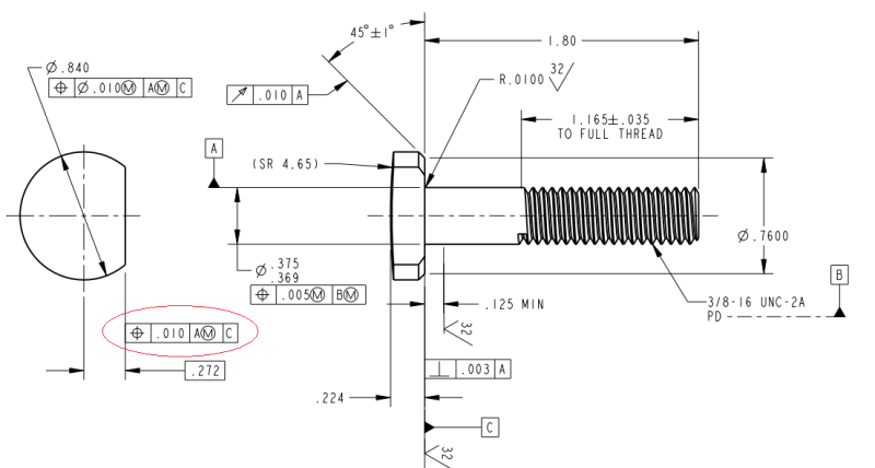
screw_cksfgr.png


I've found multiple other issues as well... The runout tolerance is total overkill on this part as that chamfer is only there to clear a radius in a molded plastic part it mates with. The surface I first mentioned really only needs to be perpendicular to datum feature C and have a relatively tight tolerance on the positional dimension to ensure interchangeability.
 
Replies continue below

Recommended for you

Is this an iso part? I vaguely recall them having some different application for position but forget details.

Does seem like it should be profile or something.

Plu8s what is datum A supposed to be?

Posting guidelines faq731-376 (probably not aimed specifically at you)
What is Engineering anyway: faq1088-1484
 
Datum feature A is supposed to be the shank of the thread. That's a good point though, I didn't notice that... It should be positioned to indicate the FoS is the datum feature.

It is an ASME-inch part, hence my confusion about the position application.
 
So datum A is meant to be the unthreaded portion, while datum C is the pitch diameter of the threaded portion?

Then Datum A is positioned relative to datum B.

It's off or potentially off in a number of ways.

Posting guidelines faq731-376 (probably not aimed specifically at you)
What is Engineering anyway: faq1088-1484
 
Ugh - yeah, Datum A is located based off of the position of the pitch diameter, datum B. That doesn't make much sense does it? The thread should be a secondary datum, or the shank should not be a datum feature at all perhaps. I suppose for the purposes of inspection it doesn't matter that the shank is measured and its position validated based off of the pitch diameter though correct?

A needs to be in line with the FoS dimension.

B should probably be positioned in relation to A, not the other way around.

C looks OK.

Profile of a Surface should probably be used for the surface currently being controlled with position. Or perhaps, because the orientation of the flat on the head diameter doesn't matter (180 deg. vs 222 deg.), we could control it's form with an appropriate size dimension and use Rule #1 to control the form.

Runout should be removed.
 
In ASME, replace position with profile (basic .272 stays)

Re:"B should probably be positioned in relation to A, not the other way around."

Ask yourself, which is driving which is driven?

I would say it is correct as is, depending by the functionality of this part/design intent.
Was designed to center it/the part (in the assembly) on B or was designed to be center on A?


While the intent might be clearer with profile rather than position, I don't think it makes any difference. The Datum A should be inline with the shank diameter as already stated. You do need the runout on the chamfer (maybe not that tight, need to know mating component(s)) but without runout there could be big chamfer on one side and no chamfer on the other, causing interference in the radius of the mating part.

I have no problem with datum B or the position of A to B.

----------------------------------------

The Help for this program was created in Windows Help format, which depends on a feature that isn't included in this version of Windows.
 
Anyone remember why splitting the datum symbol from the FoS dimension and using a toilet plunger symbol was argued for as a better idea (ISO compatibility is not sufficient)? It would have avoided the ad hoc approach taken to signifying the thread was a datum and eliminated having a datum apparently apply to the tangent of a cylinder when it makes more sense for it to be the FoS.

And how much tolerance is there for the toilet plunger to be misaligned with the FoS dimension for it to no longer apply? Is .0001 misalignment enough or does it depend on eyeballing that relationship?

Any clues on why the spherical radius is reference and there's no tolerance for its location?
 
When indicating the datum feature symbol on a cylindrical part (such as the shank above), it really doesn't matter if it's in line with the dimension arrow or not. You guys are thinking of a planar part -- then it would be a huge difference: surface vs. FOS.

I'm not staking my comment on ASME's letter-of-the-law, but what other interpretation could there be with a cylindrical feature? Could datum A be misinterpreted as, what... a tangent line across the top?

John-Paul Belanger
Certified Sr. GD&T Professional
Geometric Learning Systems
 
How better to indicate that it is the tangent than to make it unrelated to the dimension - just like the interpretation for a plate?
 
How better? To use a datum target, if that line is what was desired.

John-Paul Belanger
Certified Sr. GD&T Professional
Geometric Learning Systems
 
In any case, it's not meant to be a tangent line (Datum A), it's meant to be the shank diameter, and so should conform to the standard for consistency sake. So I will make that change. And I think that it merely needs to be visually in line with the FoS dim, or otherwise, clearly offset.

dgallup: As far as runout is concerned... Doesn't the FoS dim (45°±1°) control the chamfer enough to ensure that the chamfer is consistent throughout the entire diameter (flat excluded)?

dgallup/greenimi: I thought that position can only be applied to the centerplane or axis of a feature of size (the standard says that you need two opposing elements of a feature to control it with position)? So, I don't believe you can legally apply true position to a surface... I would think that flatness or profile would be the only way to control that feature. In actuality, I was thinking that flatness may be better than profile as we're not really concerned with orientation of the feature radially, but because we are concerned with its perpendicularity to the axis of the part, profile is the way to go I believe.

3DDave: No idea about the spherical radius... Perhaps they start with a purchased part and so it's basically reference information.
 
CH: Thanks for the link. I'll still fall back to the position that placing the datum symbol with the dimension eliminate ambiguity and that adopting the ISO toilet plunger was a huge mistake.

ModulusCT: Even if it is made from a purchased part, there needs to be some limit for the location of the feature relative to all the other features that are being created.

Belanger: Adding a datum target line would add significant geometry to the drawing; adding this interpretation does not. It requires adding a symbol to the left hand view and requires adding a top view to show that this isn't a target point. 2009 - Figure 4-45 should have applied the datum symbol to an indicator for the cone angle to eliminate ambiguity. For certain if it had been applied to either the large or small circle in the side view it would not be assumed to apply to the cone even though those are part of the conical surface.

<soapbox>
Harmonization by parroting ISO makes Y14.5 only superficially similar, in spite of fundamental differences. There was no published explanation given for parroting this element of ISO. The lack of published explanation leads me to speculate as to the motives for doing so, and I see no benefit to the users of the standard, not only because it generates ambiguity but it also takes more space on drawings, as can be seen even in this example. There should have been a really good reason to adopt a symbol from an incompatible standard.
</soapbox>
 
Dave, you should notice that I never advocated for the terribly confusing use of the offset datum feature symbol in the OP's case. All I meant was that it's more of a stretch to think of it as a tangent line than it is to simply think of it as an axial datum.

In the case of Fig. 4-45, I think the escape hatch in that interpretation is that datum A's reference in the feature control frame clearly spells out the degrees of freedom, so in that example there is no chance of misinterpretation. I guess I agree that it's still not the best way to do it, though.

John-Paul Belanger
Certified Sr. GD&T Professional
Geometric Learning Systems
 
I can often guess when a homonym is used based on other clues in a sentence, but it still is either incorrect or ambiguous.

At a first glance I would assume, absent of any other clue, it applies to the tangent plane, just like it does to one face of a width. If they wanted to apply it to the diameter, there are multiple locations that would express that exactly. It should not be required to look at any FCF to determine which feature a datum symbol refers to.

Since that's not the most likely case, and the datum location is not one that is depicted for a cylindrical feature, I would kick it back for correction rather than accepting it. It takes 2 seconds to make it match similar examples to eliminate any question of interpretation.

As an example of an ambiguous typo, I offer '2009 figure 3-3. Is [C] a plane through one face or is it in the center of the width of the tab?
 
Not sure why you dislike Fig. 3-3, datum C. It's clearly a plane formed from the top surface of the tab. It's not in line with the dimension line, which would be indicating a feature-of-size datum. No typo that I can find.

Is your beef something like "how close must the datum symbol be to the dimension line for us to call it a FOS datum?"

John-Paul Belanger
Certified Sr. GD&T Professional
Geometric Learning Systems
 
That's not a dimension line. There is no value associated with it. It's a typo.
 
Recently, I was in Indianapolis for Solid Edge University. I took a class on 2D/3D GD&T given by the gentleman who created all of the figures in Y14.5 since the 60's... I have his email. I may email him about this, ask why the plunger was adopted and if I get an answer I will post that answer here.
 
That's not a dimension line. There is no value associated with it. It's a typo.
You really are a stickler! I guess all of these figures have typos too: 1-11, 1-12, 1-13, 1-49, 1-52, 1-53, 1-54.
(And that's just in Section 1 of the standard...)

John-Paul Belanger
Certified Sr. GD&T Professional
Geometric Learning Systems
 
Status
Not open for further replies.

Part and Inventory Search

Sponsor