Continue to Site

Eng-Tips is the largest engineering community on the Internet

Intelligent Work Forums for Engineering Professionals

  • Congratulations waross on being selected by the Eng-Tips community for having the most helpful posts in the forums last week. Way to Go!

True Position Callout on Old Drawing

Status
Not open for further replies.

ModulusCT

Mechanical
Nov 13, 2006
212
Hello, could someone please have a look at the true position callout on the left-hand view in the attached image and let me know if this makes any sense at all? I'm thinking not, as it's placement doesn't seem to indicate that it is associated with any feature of size. I'm thinking that profile of a surface is the correct callout for this surface.
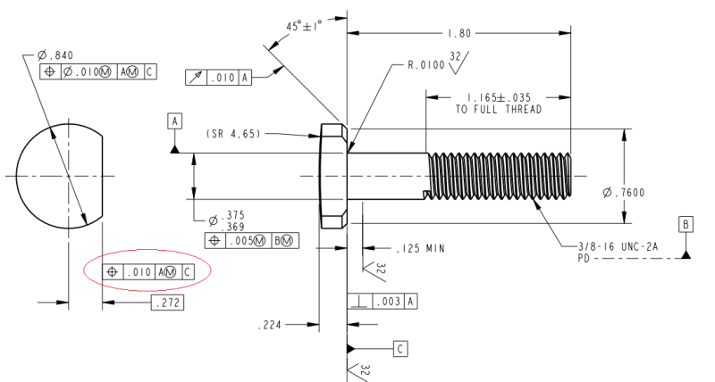
screw_cksfgr.png


I've found multiple other issues as well... The runout tolerance is total overkill on this part as that chamfer is only there to clear a radius in a molded plastic part it mates with. The surface I first mentioned really only needs to be perpendicular to datum feature C and have a relatively tight tolerance on the positional dimension to ensure interchangeability.
 
Replies continue below

Recommended for you

ModulusCT said:
dgallup: As far as runout is concerned... Doesn't the FoS dim (45°±1°) control the chamfer enough to ensure that the chamfer is consistent throughout the entire diameter (flat excluded)?

That is only the angle of the chamfer, not the size of the chamfer. The size of the chamfer is controlled by the diameter .7600. But that diameter could be way off center, hence the need for the runout control.


----------------------------------------

The Help for this program was created in Windows Help format, which depends on a feature that isn't included in this version of Windows.
 
JP - if you are going to criticize, nail it - The figure is an attempt to show the application from paragraph 3.3 indicating the surface is intended when the datum is clearly separated from the dimension.

In the 1994 version of the standard that paragraph, 3.3.2. (a), was short and to the point, as was the figure. In the 2009 version they wanted to add more examples to the similar paragraph and increased the number of surface type depictions, but still messed it up and failed to change the pluralization of the caption.

Originally, the diagram had two datum symbols, one on a surface and one on an extension line. Now it is on multiple surfaces and one on an extension line, but still is captioned "Datum Feature Symbols on a Feature Surface and an Extension Line"

Still a typo, just a different one than I called it out for, and still exceptional in that most of the diagrams that show a relationship between datum symbols and dimensions show a value for the dimension.

The rules for dimensions indicate that for unbroken horizontal dimensions the values should be above the dimension line. There is no rule describing unbroken vertical dimensions, so what to do with Fig. 1-49?

15 years between releases and yet rushed to publication.
 
3DDave,
It is really interesting to read a debate splitting hairs on a caption of a single figure from the standard (BTW, I agree it is a typo), yet at the same time see a "toilet plunger symbol" being called the "datum symbol" instead of the "datum feature symbol" [wink]

As for the original question, the answer has been already given - profile of a surface should be a choice. Position would be legal per ISO, but is illegal per ASME. Flatness tolerance does not have power over controlling location of the flat.

From other issues that have not been mentioned yet (if I see correctly), the position callout for the shank (datum feature A) does not have the diameter symbol in front of the tolerance value.
 
While we're at it, there is a surface texture symbol applied to an extension line that is associated with the .125 MIN dimension, but not an actual surface. Presumably it's meant to apply to a portion of the shank, but there are better ways to indicate this.

Also, pitch diameter is the default for a threaded datum feature, so the datum feature symbol for B could simply be attached to the horizontal portion of the leader line for the thread specification.


pylfrm
 
pmarc - you got me. I'll be more careful when I publish a standard intended for national and international use.

pylfrm - I agree on the surface texture symbol.

In looking at the drawing it appears to have been done using Pro/E or Creo. They have a terrible Feature control frame creation dialog that 'remembers' the last geometric characteristic symbol and it divides selection of material size condition modifiers from selection of the datum reference, leaving it easy to create a FCF with the wrong symbols.

Also, the reference to datum C is meaningless even if the head flat is converted to use a profile of a surface symbol.

That underhead flat diameter is apparently intended to be very precise as is the fillet radius. Not many calls for 4 place dimension values for chamfer base diameters.

Is there anything that says that increased decimal places must indicate decreased tolerance values for title block tolerances? I would find it interesting to see how long it would take to notice if the 4 place tolerance was +/-.1250 and how many would argue that I can't do that.
 
3DDave,

Is the reference to datum feature C really meaningless? ASME Y14.5-2009 Fig. 4-21 illustration (c) would imply that it is not.

As for title block tolerances, the largest I've come across for 4-place was +/-.0050 in. I wouldn't complain too much about +/-.1250 though. I'm not aware of any standards that say anything on the subject.


pylfrm
 
Ohh ugg. Yes - I'll move from meaningless to 'makes it worse.' Having a design where control of orientation can shift from the primary datum to the secondary depending on on feature size is pretty poor.

I wonder why they included the pathological '2009 example. It's an example that clearly shows how to tolerance a part so one can't be certain which feature is intended to orient the part.

It wasn't present in the '1994 version. It looks like someone looked at the '1994 example 4.18(d) and thought there was a similar problem and didn't realize that the virtual condition of [A] needs to be calculated in the primary frame of reference; that A@MMC is not necessarily the diameter for the virtual condition of [A] needed to create the B|A(M) datum reference frame. If the virtual diameter of A in B|A(M) is correctly calculated, B is always the primary orientation surface for (d).

I think the '2009 example the case is not as clear as it is presented. Absent dimensions for the features required to do the trigonometry to determine the angle of the head and the angle of motion allowed in the hole the condition can't be verified, so (c) is not a done deal; even at LMC for the feature used for A the underside of the item may not lie flat as depicted.
 
I would assume (with all the incumbent possible errors) that the bolt is inserted so that the flat mates with a corresponding feature that prevents rotation and a nut is tightened on the other end.

----------------------------------------

The Help for this program was created in Windows Help format, which depends on a feature that isn't included in this version of Windows.
 
3DDave,
You mentioned fig. 4-24 in the other thread about the drawing with vague general notes. I agree with your observations about fig. 4-21(c), but does it mean that in your opinion datum features scheme/sequence shown in fig. 4-24 falls into "that makes it worse" category too? Would you recommend changing datum feature order in fig. 4-24 to avoid "having a design where control of orientation can shift from the primary datum to the secondary depending on on feature size"?
 
pmarc,

I only dislike the 4-21(c) because it depicts that LMC datum feature B will be certain to control the orientation of the part, when that is not always the case. 4-24 doesn't do that, so it seems OK for the purpose it is used for.

As an example of another pathological case*:

Picture a shaft with a loose fitting thin washer and parallel to the shaft is a pin. The washer has a hole that fits closely on the pin and both the pin and shaft are set into a planar surface.

One could identify the bore of the washer as datum feature A and one face of the washer datum feature B.

Set the location tolerance of the hole at 0(M) | A | B, where the MMC size of the hole was the same as the MMC size of the pin at 0 position error. It is possible that the washer will end up flat against the planar surface, but it isn't necessary.

If the fit of the washer is loose enough, an acceptable solution might be the pin hole is a 30 degrees from perpendicular to the face of the washer in order to fit and the washer makes only point contact with the planar surface, meeting all requirements.

Some would argue that B should control the orientation for this example, but that's not what the FCF calls for. Any solution that allows the washer to fit over the shaft and contact at least one point on B is compliant as long as the pin fits the hole, even if mechanically is seems nonsensical. If the other solution is desired, one needs to select a different FCF.

*Result of an actual discussion. The person suggesting A|B was holding that since the shaft assembly step was first before contacting B, the datum representing the shaft had to be first as well and it was a loose fit anyway.
 
Status
Not open for further replies.

Part and Inventory Search

Sponsor