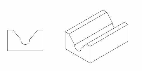
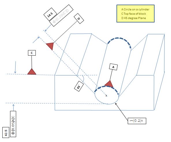
Hello everyone. As far as I know, True Position can only be applied to a feature of size such as circles, cylinders, planes...etc. However I lately came across a drawing with TP's are pointing to a non-feature elements to be controlled. Please take a look at the sketch attached and let me know how would you measure these two true positions (preferably using Calypso software with Zeiss CMM). Any help is greatly appreciated.
Navigation
Install the app
How to install the app on iOS
Follow along with the video below to see how to install our site as a web app on your home screen.
Note: This feature may not be available in some browsers.
More options
Style variation
-
Congratulations MintJulep on being selected by the Eng-Tips community for having the most helpful posts in the forums last week. Way to Go!
You are using an out of date browser. It may not display this or other websites correctly.
You should upgrade or use an alternative browser.
You should upgrade or use an alternative browser.
True Position of non-feature of size
- Thread starter tainest77
- Start date
- Status
- Not open for further replies.
- Thread starter
- #3
Burunduk, Thank you for your response. The drawing actually is not actual, instead is a hand sketched one just for illustration purpose. I agree it's not one of a standard one but just to illustrate as I said. It's a front view of a 0.5 degree plane that transitions into a 45 degree plane in turn transitions into an arch of about 30 degree and then datum C plane again. Above datum C the Circle does not really exist. It's really me did not do a good job making the sketch because I am not allowed to post actual drawing here. Please let me know if more clarification about the sketch.
Regards.
Regards.
- Thread starter
- #5
Think of the part in the sketch as a V-block shape gage, metrology and QA departments use for different measuring purposes. The only difference though: instead of the two faces of the “V” meet at an intersection line, this latter intersection feature is a small internal cylinder. Everything is symetrical from this cylinder axis. Datom A is this Cylinder itself. Datum C is the top face of the block but instead of being perfectly horizontal, it’s inclined 0.5 degrees to your right side when looking strait at the block. Datum D is the 45 degrees left face of the block. If you make a perpendicular between the cylinder axis and datum C, the depth of this perpendicular is the basic dimension 14.5 mm shown. As far as standard base alignment XYZ: X coincide with the cylinder axis, Z axis is the perpendicular to it going vertical and Y axis is obvious. Now the first True Position is pointing to the lowest Z value feature (if it’s a feature at all)in the cylinder perimeter (not the bottom face). The second one I guess is is pointing to the perpendicular depth I mentioned earlier. I hope this Clarify a bit about your question.
Regards.
Regards.
Burunduk
Mechanical
- May 2, 2019
- 2,580
The datums are clearer now but the drawing position tolerance requirements are still unclear. This definitely has no meaning in ASME. Maybe the intent is to control the location of the flat faces (while "self-referencing"?). ISO allows locating flat surfaces by position but the feature control frame is not supposed to be attached to a dimension line. Either someone else in this forum can enlighten you or you will have to ask the drawing provider for the intent.
- Thread starter
- #7
Yes we use ISO standards. We get drawing with flat surfaces being located by TP a lot. However in this particular case TP assigned to a distance between Datum D (45 deg face) and datum A (center cylinder) with self referencing of datum A! I find it odd and confusing. I am not sure what's the intent here. Please take a look at a new attachment for more clarification.
Regards.
Regards.
Think of the part in the sketch as a V-block shape gage, metrology and QA departments use for different measuring purposes.
Is the drawing supposed to be of the cylindrical part by itself? If so, any references to a v-block in the dimensioning scheme I would say is extraneous and possibly inappropriate unless this is supposed to be an assembly drawing where the v-block is attached to the cylindrical part in the actual functional assembly and not just during measurement.
I don't recommend inclusion of measurement tools/processes in a drawing, however putting aside some of the inherent issues with utilizing v-blocks during measurement it is not uncommon to see notes such as "cylindricity of X feature measured with 90deg v-blocks". The v-block still should not show up in the dimensioning scheme even in that case unless one can come up with a convincing reason why.
Since you've specifically noted measurement will occur on a CMM the reference to a v-block is even more confusing. Or perhaps your initial sketch showing just the cylindrical feature is misleading and the drawing is actually supposed to be of the v-block itself? Some clarification is definitely needed as its not clear what the drawing should refer to. I'm no ISO expert but I think these specifications are problematic no matter what standard you are pursuant to (as Burunduk noted, in ASME these specifications are uninterpretable).
tainest77 said:https://www.eng-tips.com/viewthread.cfm?qid=464338,[/URL] 10 Mar 20 15:01]And also to clarify some confusion: Think of this whole V-Block and cylinder as a one whole single piece with the cylinder being an internal feature, meaning hallow instead of a pin per say. Also only the first bottom half of the cylinder exists, the top 180 is a dotted half if you will.
This only somewhat clarifies things.
Is something like the below what you mean? If so, can you please describe how the part is expected to function/mate? Does it behave like a standard v-block ie: contact is only expected on the planar faces? If so the cylindrical portion is only for clearance and I would say should not be a datum feature. It should be driven from other features not a driving feature.

- Thread starter
- #11
Chez311 yes—thanks a lot for your feedback. I was looking for something like that online but could’t find one. Also reworked the previous one I posted to clarify a bit. And by the way this is one whole single block (not assembly). So are these TP legal? What’s the intent here? What feature is intended to be controlled? How about DRFs? I am confused. Any help is highly appreciated.


What’s the intent here? What feature is intended to be controlled? How about DRFs?
Either you or whoever produces the drawing must determine these things. Without knowing how this part is supposed to function/mate with other parts we can only guess. Designation of datum features will typically follow from function.
- Status
- Not open for further replies.
Similar threads
- Question
- Replies
- 6
- Views
- 10K
- Replies
- 25
- Views
- 3K
- Locked
- Question
- Replies
- 16
- Views
- 6K
- Question
- Replies
- 9
- Views
- 1K
- Locked
- Question
- Replies
- 20
- Views
- 9K
