Continue to Site

Eng-Tips is the largest engineering community on the Internet

Intelligent Work Forums for Engineering Professionals

  • Congratulations SSS148 on being selected by the Eng-Tips community for having the most helpful posts in the forums last week. Way to Go!

Truss connection 2

Status
Not open for further replies.

BAGW

Structural
Jul 15, 2015
392
Hi,

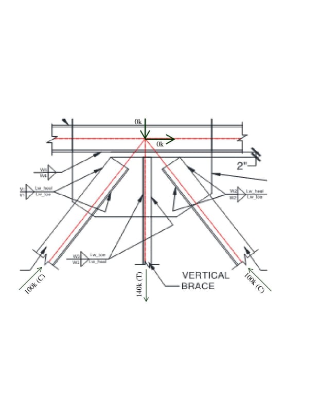
See image below. The diagonals are in compression and vertical is in tension. When I sum up all the components for the gusset to chord design, the forces adds up to be zero. This does not make sense. How do you come up with the forces for the gusset to chord design? I dont think splitting the plate into half and checking for the local forces is correct.

Any thoughts. Can I just design for 140k of vertical force?

Thanks
Document1_hbduye.jpg
 
Replies continue below

Recommended for you

This would be at midspan, where the diagonal web members do not contribute to chord force--they balance each other.

Design the gusset plate in the usual manner--draw a free body diagram with all of the forces, and go from there.

DaveAtkins
 
The change in chord force on either side is zero. This is how the free body looks. I am not sure what you are suggesting. I dont think designing the half side of the plate for shear (70k), moment (70 x ecc), axial (70k) is the right way to go. I am just interested in gusset to chord connection forces.

Document1_mjugzw.jpg
 
For the load case you are showing, the net force is zero between chord and plate. Under unbalanced load conditions, the force is usually not zero but is still pretty small. There is not much design required. You need a nominal weld just to hold everything together.

BA
 
Theoretically the gusset plate to chord connection is not required, since there is no net reaction at the interface. So design the gusset plate based on the individual force from the diagonal, and tension from the vertical strut. Then, for chord-gusset connection, conservatively design half of the gusset plate for the compressive force from the diagonal.
 
retires13

This is what I wanted to avoid "for chord-gusset connection, conservatively design half of the gusset plate for the compressive force from the diagonal". If I use the half the gusset plate length, the weld resulting from the bending (fb) will be conservative by factor of 4. I think thats very conservative. I thought about this but the connection is getting very long.

I think meeting the min weld requirement per code must satisfy this. I think this is what BAretired is suggesting too.
 
There is no need to lengthen the plate, as the dimension of the gusset plate should be already determined by the design check on the connections between diagonals, and strut in the first step of design, now the consideration is only set on throwing some force into chord-gusset interface to ensure the stability of the free edge of the plate. For the plate experiences high compressive force near the top, which has no restraint, I personally prefer to stiffen the edge through weld design for the thrust.
 
A tension of 140k is an unusually large force for the vertical. Do you have a heavy load suspended below it?

I would like to revise what I stated in my last post. There is a 70k compression and a 70k shear in the plate in the central region. The plate must be capable of resisting those forces without buckling. If the plate needs help from the chord to resist those forces, the weld may be more than minimal.


BA
 
For shear and axial can I use half the plate of gusset and for moment resulting from the shear can I add them up and use the full length?

fv = Vu / (2 x L/2)
fa = Nu / (2 X L/2)
Fb = (Mu1 + Mu2) x 6 / (L^2) x 2
 
Hi,

Not much to add to the discussion, I just have one question: Are there no transfer forces from the roof/floor system?
 
This paper will help, if you are sizing the gusset plate. Link
 
Nope there is no transfer force (there is force applied at the lower portion of the vertical). Also I am using K=1.2 for the gusset plate buckling check and if I remember correct K=0.65 for chevron braces.

I am just concerned about the bending stresses required for weld. Even in the attached link, AISC recommends using full length for moment and shear resistance. Which I completely agree.

I am confused in my case as all forces adds up to be zero.

 
BAGW,
I think it will be useful to have more information about the general configuration of the truss/structure in order to provide more useful guidelines.

The detail you show seems like the typical case of 'maximum force envelope' reported in most design drawings. While these forces represent the most critical condition for the design of the connection between each web member and the gusset plate, they do not represent the actual force distribution in the structure and tend to overlook transfer forces. So, if that's the case, you must exercise your own engineering judgment to come up with a rationally conservative load path for design. In other words, the force distribution presented in the design drawings may not be sufficient or adequate for connection design unless separate design forces are provided for each load case.

 
PROYECTOR,

Just looking a gravity truss with dead and live load. The forces I have shown in the image above is just a single load case of D+L. Having a really hard time to digest the connection to the top chord. What forces to be used at to top chord connection?

I was just planning to go ahead and design the connection for 140kips as thats the laod applies with half the gusset length.

Document1_wgdv7o.jpg
 
I think you are tasked to design the connection while design don by others.

I usually started with sizing the plate, then move to connections. For chord-gusset connection, provide weld strength of a half plate for 70 kips shear force, or use the minimum weld size, whichever is larger.
 
Well, for the distribution of forces shown it is clear that theoretically there is no need for the connection between the gusset and the top chord of the truss. The forces are transferred from the vertical element to the gusset and from the gusset to the diagonals, without the top chord being affected. As you have already been told, only nominal weld is required. I think that would be enough to keep the pieces in place during erection and to resist any demand resulting from plate buckling. However, it is advisable to provide the connection for a minimum stregth level (there are no perfect structures and perfectly balanced force distribution are an utopy). I would apply a similar procedure to that suggested by retired13.


retired13,

I am doing the design with connections. So I know what the loads are and where are they coming from.

I agree with the steps you are mentioning. When you say 70kips shear force, are you pointing down to the one below. Is there a reason why eccentricity from the shear and the axial force is neglected?

Document1_kqvvhw.jpg


PROYECTOR,

Agreed. There is no perfectly balanced forces. Thats why I was trying to atleast design the weld for the force in the vertical component. If that makes sense. Or even neglect the componet directions, add both the shear and calculate the moment resulting from the shear and use the full length of the plate to check the weld.
 
That's why I mentioned design step. It seems you are jumping around. As addressed before, the forces are in equilibrium within the gusset plate, if the plate is adequate, your design is done. But, the thrust from the diagonals produces compression near the upper free edge, so, it reasonably be conservatively stiffened by a connection weld equal to the horizontal compressive force. Note this is a judgement call, you may use other arguments to design the connection, such as construction tolerations, consider things do not turn out perfect as intended.
 
BAGW,

Designing the weld for the 140k vertical force would imply that the top chord would be subject to bending, so that would not be a very plausible load path. In the event of a significant unbalanced force condition, this would probably occur in the horizontal direction. Therefore, the approach of retired13 seems more appropriate to me. I think the moment resulting from the eccentricity can be neglected in this case.

Note: The only way that a vertical force is transferred between the gusset and the top chord is that another member provides a load path for that force (a post, a hanger, etc) or there is an element transferring a reaction at that node (a purling, a beam, another truss, etc).
 
Oh ok.. I understand now.. You are suggesting just to check the weld for the horizontal component of the diagonal as a thrust force.. this is just a sanity check force and has got nothing to do with the eccentricity bbtetween the weld and the WP.. correct.. or come up with some other ways of checking the welds, something in terms of what I have mentioned above
 
Status
Not open for further replies.

Part and Inventory Search

Sponsor