Continue to Site

Eng-Tips is the largest engineering community on the Internet

Intelligent Work Forums for Engineering Professionals

  • Congratulations waross on being selected by the Eng-Tips community for having the most helpful posts in the forums last week. Way to Go!

Truss Reactions 2

Status
Not open for further replies.

Sparkes1992

Structural
Nov 3, 2016
29
Hi Guys,

I've been modelling a simple truss in the program spacegass with a dead and live loading on the top chord. I seem to be getting large horizontal reaction forces. Shouldn't the bottom chord of the truss be acting in tension hence stopping the top chord from opening up? How do i ensure that the perimeter beam that the trusses are sitting on recieve no lateral force? Any help would be much appreciated.

Jack
 
Replies continue below

Recommended for you

I'm not familiar with the software you are using but it sounds like you have your reactions as "Pin, Pin" rather than "Pin, Roller". You need to release the lateral restraint at one of the supports to allow the bottom chord to take the tension otherwise it will just go straight into the reaction.
 
Ahhhhhhh awesome, thanks mate! I'm not sure how i would go about ensuring that the connection acts like a roller. Any suggestions? :)
 
And if i pin one side, shouldnt all of the lateral force be attracted to that pinned side?
 
Is the truss made from concrete members? Or is it a steel truss being supported by a concrete member? If it's the latter, you can detail the connection on one end to allow lateral movement.

In a pin-roller situation with only vertical loads, you won't get any horizontal reactions. The horizontal loads are internal forces within the truss members filtering out and finally ending up as an axial load in outermost intermediate member.


Hi Trenno, thanks for the response. It's a steel truss supported on each end by a steel member. If I pin one end and roller the other, the pin should take all lateral loads shouldn't it?
 
The only reason you are seeing horizontal loads when you adopt a pin-pin situation, is because each end of the truss cannot move in the horizontal direction. Now when the truss wants to deflect, under vertical loading, the bottom chord wants to 'kick out' but because the ends are all locked up that's why you're seeing those large lateral reactions.

Now when you have a pin-roller, the reason why you don't see any horizontal reactions is because the truss bottom chord is allowed to 'kick out' and isn't restricted to expand in the horizontal direction. This lateral deflection essentially alleviates the horizontal reaction.

 
Once again thanks for the response trenno. If a lateral wind load were to be applied to the truss, wouldn't the pinned side of the truss essentially have to resist this force? Otherwise wouldn't the truss 'slide'?
 
Yes, that is correct. If you apply horizontal loads, the horizontal reaction will be all at the pinned end. But that is only for analysis purposes. In the real structure, depending on how it is built, the force may be divided between the ends.
 
Cheers for that hokie. So my problem is I didn't want to have to design the beam which the truss is sitting on for biaxual bending. I'm guessing now my best bet would be to design these perimeter beams to wind loading in the minor axis and dead in the major?
 
The usual process goes something like this:

1) Decide where you want the lateral reactions to go. This can be the left end of the truss, the right end of the truss, both ends of the truss, the roof diaphragm, or any number of less common scenarios. Make your decision based on available strength, available stiffness, detailing convenience, and your own preferences as he designer.

2) Whatever provides the lateral support for your truss, usually we design that stuff separately from the truss itself, using the reactions from the truss.

3) Design the truss using one of these approaches:

3a) If lateral effects are small relative to gravity effects, ignore them and make one end of your truss pinned and the other fixed arbitrarily.

3b) If you're confident that you know where the lateral loads will go, or where you want them to go, model your truss supports to reflect that.

3c) If you're unsure of the load path and want a little more conservatism, place the lateral support (pin) as far from the source(s) of the lateral load as possible to maximize the number of truss members involved in resisting the lateral load. Note that this may not be universally conservative in all cases and some case specific engineering judgement is required.

I'd recommend posting some sketches of your truss and and the framing upon which it bears (plan and section). You've got some wildly competent structural engineers participating in your thread. With some additional information in hand, they'll tell you just what ought to be done and why. They might even agree.

I like to debate structural engineering theory -- a lot. If I challenge you on something, know that I'm doing so because I respect your opinion enough to either change it or adopt it.
 
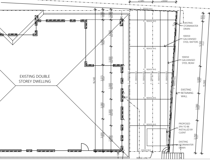
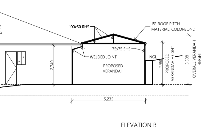
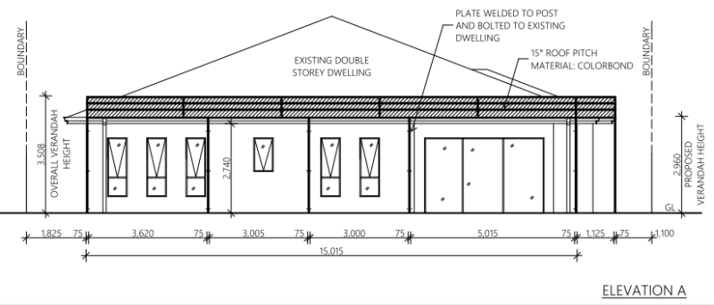
KootK, excellent post mate, thank you very much! Ok, so ive attached some sketches below. Just ignore the member sizes for the moment. All members in the truss are to be 100 x 50 RHS welded together. The trusses are going to sit on the perimeter beams with a cap connection with a bolt either side - acting like a pin connection. The columns are slightly offset from the perimeter beam and are bolted to an existing house on one side.

What i wanted to do was put as little lateral load into the perimeter beams as possible. I'm just struggling to model this at the moment. Any help would be fantastic.


Elevation_B_v07pgs.png

Elevation_A_udjpsg.png

Plan_View_zgq4lp.png
 
the left hand support (beside the house) looks pretty "flaky" ...

it looks like part of your problem is having an unobstructed face (away for the house, with just some vertical posts). So the lateral loads have to be reacted at the house, unless you make these posts cantilevers (maybe the lateral loads are small ?). Maybe add a truss in the horizontal plane to take the loads towards the house side ?

are you trying to minimise the interaction with the house ? why not tie into the roof structure (as shown, rafters and such) ?

another day in paradise, or is paradise one day closer ?
 
Like rb1957, I think that your lateral support reaction is probably at the left end of the truss at that whacky column that I'll leave in your capable hands.

I like to debate structural engineering theory -- a lot. If I challenge you on something, know that I'm doing so because I respect your opinion enough to either change it or adopt it.
 
I agree that the column looks 'flaky'. Also, Elevation A shows the fascia to be level whereas the plan seems to suggest it is sloping down toward the north.

BA
 
I was planning on bolting the posts into the existing brickwork. Yeah the the drawings are just s rough sketch st the moment. What do you guys mean by flaky? I was more so just trying to understand yh loading path from the trusses into the perimeter beam. My question is do I need to put the lateral load caused by the dead load from the truss into the perimeter beam? Shouldn't the bottom chord prevent this from happening even though it's pin pin at each end? I thought I'd only need put the wind lateral load into it.
 
ok, looking at the truss in isolation, looking at Elev B, how much lateral load (acting to the right) will come out at the RH side (where you have only vertical posts) ? IMHO, not much, so your structure will "naturally" react this load on the LH support.

I think we were also talking about the "other" lateral load (out of the page on ElevB), which again is naturally attracted to the house side.

the kinks in your LH support make it look "flaky". do you intentionally choose not to support on the existing roof ? why ?

another day in paradise, or is paradise one day closer ?
 
OP said:
Shouldn't the bottom chord prevent this from happening even though it's pin pin at each end?

This is only true if your truss is modelled pin-roller.

I like to debate structural engineering theory -- a lot. If I challenge you on something, know that I'm doing so because I respect your opinion enough to either change it or adopt it.
 
I almost spit my coffee out when I saw that column. I expect making it structurally adequate would be difficult.

The support on the left looks flaky because it's not a direct load path, it develops a moment in the column, needs a lateral reaction at the ground, and would potentially have a lot more compliance than an appropriate tie into existing structure, or a straight column between the truss end and the foundation.

Problems that could arise from this are:
Applicable code/standard?
expensive design, detailing & fabrication of the dog legged column to make it structurally adequate.
Excessive motion of roof under dynamic loading, paint/drywall/plaster cracking problems.
Failure and other bad things.
Issuing extra prints if people actually do spit their coffee when they see it.
 
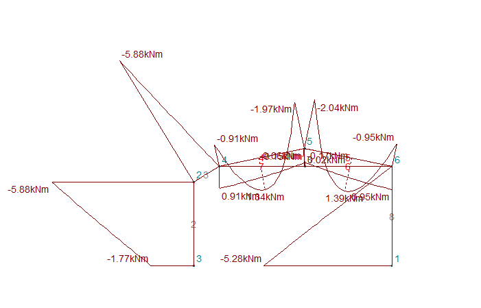
I didn't want to tie it into the existing roof because i don't know how its trusses are tied to the top plate. I dont think the bending in the column is that bad (see below). I should note that the structure isn't clad on the walls so the loads arent incredibly high.

Moon161, as long as i have modelled it correctly with the appropriate loads, how can it fail?

Bending_Moments_ytav50.png
 
Status
Not open for further replies.

Part and Inventory Search

Sponsor