Continue to Site

Eng-Tips is the largest engineering community on the Internet

Intelligent Work Forums for Engineering Professionals

  • Congratulations waross on being selected by the Eng-Tips community for having the most helpful posts in the forums last week. Way to Go!

Trying to determine airflow through a pipe when vacuum is applied 1

timsch

Mechanical
Oct 27, 2009
180
Hello All. Non-piping engineer here.

I am trying to determine what airflow I have through a section of pipe attached to what we call an exhauster. Searching for exhausters online doesn't come up with much, so I don't know how common they are or if they're known by some other term. Our exhauster is a T-shaped piping assembly with a venturi at the cross of the tee. An air line from a compressor is attached to one side of the tee and blows through the other side. A vacuum is created in the trunk of the tee, pulling air from below.

For an R&D project, we used this to pull hot air from the top of a furnace up through the tee, which had surface mount temperature sensors attached. For the analysis, I need to determine the flow rate through the trunk. I thought it would be a relatively simple calculation, and perhaps it is, but not being used to fluid calculations, I've not been able to get a clear idea what I need to do from all of the various resources I've looked at.

Air temperature is = ~1300F
Pipe = 1-1/2 Sch.40, 3' long, open at the bottom
Vacuum = 3 inHg (g)

I thought that it would be relatively trivial to convert vacuum to a pressure differential, but I'm not so confident that I've done it correctly.

Looking at this conversion table, I estimate that 3 inHg (g) may be around 10% vacuum, as well as around 13 psia.

Since I am exhausting to ambient, I can consider the pressure differential to be 14.7-13 psia = 1.7 psi

I'll assume no pressure gradient along the pipe for so short a length, and no friction factor for the same reason.

I've run across many different proposals on how to solve this, but using Bernoulli's Equation seems that it would be sufficient.

Let me know if you have a better way to determine the flow rate for these conditions.
 
Replies continue below

Recommended for you

I am not that familiar with the device but it is basically a venturi arrangement. You can find information on the internet by searching "venturi exhaust tee systems".

3 inHg is the pressure differential at the venturi which causes the flow to be exhausted into the tee connection of the venturi. The 3inHg is caused by the main flow from the blower in the main pipe flowing through the smaller area section of the venturi which causes a reduction in pressure which forces the exhaust air into the tee section. 3inHg is equivalent to 1.5 psi pressure differential between venturi pressure and pressure of the air to be exhausted, if the air to be exhausted is at atmospheric or 14.7 psia. The flow of exhaust air into the tee will be based on a differential pressure of 1.5 psi so that this will be the pressure loss available to produce the flow. The pressure loss is based on the exhaust air inlet configuration which will be a combination of pressure drop due to friction and velocity increase.

You may be able to calculate yourself knowing the configuration of the exhaust air inlet but I the manufacturer of the venturi fitting should have tables that give the exhaust air flowrate for given main air flowrate and vacuum developed in the venturi section.
 
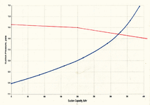
Thanks for the replay. I do have a table (attached) from the manufacturer, but it is greek to me. The suction pressure on the Y-axis tops out at 15.5 psia, which I assume is near full vacuum since the maximum suction capacity is at that value. My suction pressure is much lower than that, if I'm reading it correctly, so not of much use to me.

I should have noted that I removed the lower section of the tee at the flanged connection and put on a blind flange with a dual pressure/vacuum gauge. Running the air (@ 126 psi) through the exhauster, I measured the vacuum. At this point, I'd think I could focus only on the lower section of pipe that attaches below the exhauster and treat as simple air flow through a section of pipe with a pressure differential between the ends.
 

Attachments

  • 2400170 CURVE.pdf
    54.6 KB · Views: 17
Trying to figure out flow pulled through a venturi can be dicey. At best, flows estimated will have a large error.

Suggest use of a hot wire anemometer for this - not expensive.
 
Trying to figure out flow pulled through a venturi can be dicey. At best, flows estimated will have a large error.

Suggest use of a hot wire anemometer for this - not expensive.
I've already measured the vacuum resulting from the flow through the venturi. I should be able to leave the venturi out of it and treat it as simple air flow through a section of pipe with a pressure differential between the ends.

It'd be nice to have the hot-wire anemometer, but it was a one-time test so calculations are my only option now.
 
The way I see that graph you attached is that the suction pressure indicated is the pressure that exists at the inlet of the suction. The suction is the lower section of the tee you refer to which sucks in the exhaust gas into the venturi section and has nothing to do with the main flow pipe.

So what the chart shows is that at 12 psia pressure of the gas you are trying to get to flow into the exhaust the flow is zero. Therefore the normal operating venturi pressure (in the venturi itself) must be 12 psia or 2.7 psi vacuum at the design flow of the compressor/blower since if the gas you are trying to suck in is also at 12 psia there is no flow.

As the suction pressure increases the flow also increases. The graph shows a maximum suction pressure of 15.5 psia (or 0.8 psig assuming atmospheric pressure is 14.7 psia) the flow is about 380 lbs/hr (I assume this is the flow in terms of air at standard conditions?).

You indicate you have a 3 in Hg vacuum. I don't know where this pressure is measured? If it is in the vessel you are exhausting from then this would be the suction pressure. So 3 inHg gage vacuum pressure is 14.7-1.5=13.2 psia suction pressure which should give a exhaust flow of about 225 lbs/hr per the graph.
 
Last edited:
3 in Hg means 1.47 psi vacuum which is 14.7-1.47=13.23 psia suction pressure.

From the give curve, it appears that suction capacity will be around 220 lb/h.

But these parameters will be valid for a particular motive air pressure, which will be mentioned in the ejector specification.

As the production of compressed air is expensive, it may be cheaper to purchase a vacuum blower(roots blower) which can take care of given vacuum requirement.

However, if you already have adequate spare capacity available in existing compressed air system (if there is any) then that option may be cheaper.
 
Suction flow, for a given venturi design, would be a function of suction pressure, suction gas temp, motive gas pressure and motive gas flow. The influence of the latter 3 is not shown on your graph.
 
The way I see that graph you attached is that the suction pressure indicated is the pressure that exists at the inlet of the suction. The suction is the lower section of the tee you refer to which sucks in the exhaust gas into the venturi section and has nothing to do with the main flow pipe.

So what the chart shows is that at 12 psia pressure of the gas you are trying to get to flow into the exhaust the flow is zero. Therefore the normal operating venturi pressure (in the venturi itself) must be 12 psia or 2.7 psi vacuum at the design flow of the compressor/blower since if the gas you are trying to suck in is also at 12 psia there is no flow.

As the suction pressure increases the flow also increases. The graph shows a maximum suction pressure of 15.5 psia (or 0.8 psig assuming atmospheric pressure is 14.7 psia) the flow is about 380 lbs/hr (I assume this is the flow in terms of air at standard conditions?).

You indicate you have a 3 in Hg vacuum. I don't know where this pressure is measured? If it is in the vessel you are exhausting from then this would be the suction pressure. So 3 inHg gage vacuum pressure is 14.7-1.5=13.2 psia suction pressure which should give a exhaust flow of about 225 lbs/hr per the graph.

I appreciate the responses, but I think that I've not been clear enough about my conditions. Sorry for any confusion.

"The suction is the lower section of the tee you refer to which sucks in the exhaust gas into the venturi section and has nothing to do with the main flow pipe."

It is this only in this lower section that I'm looking for flow values, not in or after the venturi section. The furnace is at negative pressure, but only 1" H2O, so practically negligible, therefore I'm considering the furnace to be at atmospheric pressure. So, I have 3 inHg vacuum being pulled on the suction pipe coming out of the furnace up into the exhauster containing the venturi. The flow from the suction pipe once it combines with the compressed air flow coming out of the venturi is also not in the scope of what I'm trying to calculate.

So, atmospheric pressure just below the suction pipe and 3 inHg at the top of that pipe. After a vacuum to pressure conversion of measured values, would the Bernoulli equation be correct to use, or is there a better way to calculate it?
 
In a typical fluid flow situation there will be pressure changes caused by the Bernoulli effects (velocity changes) and also losses caused by friction. Depending on the situation, one of these may be dominant and the other can be ignored without introducing too much error. In your situation, by my calculations (which I will show below) the two effects are almost equal and should both be considered. I have written this article which you may find helpful discussing the interplay between Bernoulli and friction. (Disclaimer: the article is hosted on a web page for a commercial product in which I have an interest.)

I have taken the pressure in the furnace to be -1" H2O (14.66 psia) and the temperature to be 1300 F. This gives a density of 0.02247 lb/ft3 and a viscosity of 0.0427cP. The opening into the 1.5" Sch 40 pipe was taken as square. The pressure difference between the furnace and the top of the 3 ft exhauster leg (i.e. the suction of the venturi) is 1.46 psi.

In order to evaluate the velocity changes using Bernoulli we need to be able to calculate the velocity at the top of the exhauster leg. I have used the 1.61" ID of the pipe to do this, but if the opening into the venturi itself is significantly smaller than this it would introduce an error into my calculations. The velocity in the furnace is taken as zero.

The friction effects come from two sources. The first is the entrance loss as the gas is drawn into the pipe. If this entrance is belled or rounded it would cause smaller losses than the square entrance I have assumed.

The second friction effect is the surface friction inside the pipe. In this case it is not negligible because the gas velocity is high - around 550 ft/s.

The total friction loss (entrance plus wall) is 0.8 psi and the pressure loss caused by the gas acceleration is 0.66 psi, making up the total of 1.46 psi.

This calculation indicates the air flow to be 600 lb/hour, which is much higher than what your graph indicates and this casts doubt on the measured vacuum of 3"Hg.

If you want to do this calculation yourself you can use the Darcy-Weisbach equation which is intended for incompressible fluids (i.e. liquids) but which would be reasonably accurate in your situation because the pressure (and therefore the density) of the gas varies less than 10 % of the absolute pressure value.
 
A sketch (or photo) of your arrangement with conditions and flow directions marked would provide some clarity. 3 in-Hg velocity pressure is really cranking along and no doubt has a lot of friction loss.
 
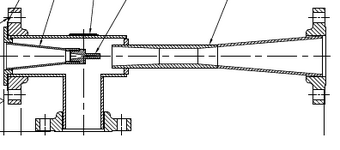
Here's a drawing of the exhauster itself. The bottom flange is what I blanked off measured the vacuum in a separate test run. The air compressor line was input on the left side flange connection.

What is not shown is the length of pipe used during our R&D tests that connects to the bottom flange that then goes down through the roof of our furnace. The flow through this pipe is what I need to calculate. Air is input from the left and exits out the right. Furnace air is pulled from below and also exits right.

exhauster.png
 
Last edited:
I get about the same results as Katmar. If the total differential pressure is 1.46 psig (3 inHg) then at 600 lbs per hour (2.18 SCFS) the pressure drop will be equal to the available drop of 1.46 (3inHg) as you indicate between the entrance of the pipe and the end (top) of the pipe. This based on the following:

Frictional drop across entrance of pipe at K=0.78 = 0.57 psi
Friction drop in 3 feet of pipe = 0.16 psi
Pressure drop due to an approximate isentropic expansion at pipe entrance to V=550 ft/sec = 0.72 psi (From 14.66 psia @ 1300 deg F to 13.94 psia @ 1274.8 deg F).

However if your graph is correct then what it indicates is that at 14.66 suction pressure the flow is about 350 lb/sec. At 350 lb/sec I get the following pressure drops:

Frictional drop across entrance of pipe at K=0.78 = 0.18 psi @ V=310 ft/sec
Friction drop in 3 feet of pipe = 0.05 psi
Pressure drop due to an approximate isentropic expansion at pipe entrance to V=310 ft/sec = .22 psi (From 14.66 psia @ 1300 deg F to 14.4 psia @ 1292 deg F)

Total pressure drop in pipe = 0.45 psi which is a lot less than 1.46 psi pressure drop.

If you measured the pressure to be 3inHg vacuum at top of pipe with pipe removed and blind flange this would be pressure at venturi at design flow of compressor. I am thinking there is an additional orifice at end of pipe before the flow enters the venturi section that produces an additional pressure drop if the flow graphs you attached are correct.
 
I posted my reply before I saw your post with the sketch of the exhauster. There does not appear to be any additional restriction at the inlet. It is not really a venturi but more like an eductor with different pressure/flow characteristics than a venturi, although I am not that familiar with it. An eductor I believe more pulls/educts the air into the flowstream by the jet velocity action so flow is not strictly proportional to pressure in nozzle chamber.
 
Last edited:
I apologize if I've misled anyone with wrong terminology. After seeing the drawing, does that change anything with the calculations you've given?
 
More correctly what you have appears to be an "air ejector". I believe that the pressure you measured with flange blinded would result in measurement of the maximum suction pressure in the jet chamber during no flow in the suction, however there is an additional pressure drop when there is flow across the chamber entrance. If you measure a pressure with flange blinded at no flow the pressure at the same point during flow will be higher since there is an additional pressure drop/flow restriction to get the flow into the chamber flow area from the inlet flange connection. I am not that familiar with air ejectors though but I would just go by the manufacturer's flow curves.
 
Last edited:
By chance can you install a flowmeter on the discharge line ( annubar or Pitot tube) or measure the velocity to get access to the flow?
To me this could be the best way to get reliable data.
A third-party contractor should be able to support.
Good luck.
Pierre
 
Sizing an air ejector is very complicated as only Bernaulli and friction equations are not enough. Here are some of the additional complexities.

1. The suction air and motive air mixes in the nozzle chamber. This mixing may introduce significant energy loss(even though momentum is conserved)
2. The diffuser at the exit will introduce the maximum loss, which can be estimated from empirical fluid dynamic equations.
3. Friction losses at walls which are already discussed above.
4. The flow at nozzle exit (sometimes at diffuser exit too) is expected to be supersonic, introducing complexities like shock waves and connected losses.

The air ejector design is a specialized field and involves lot of labor. So you may discuss this with some air ejector designer and manufacturer.
 
I did not pick up that the vacuum of 3"Hg was measured at zero suction flow with the inlet blanked off. I feel a bit better seeing that Snickster also missed it initially but when my earlier calculation fell so far off the curve I should have been more suspicious.

Anyway, we are now in a position to make a much better estimate. The problem is basically the same as when you want to determine the operating point for a centrifugal pump and you have to find the point where the pump curve and the system curve intersect. You have the pump curve that was issued by the supplier so we just have to generate the system curve.

I assume that the pump curve was generated by the supplier knowing that the suction gas was at 1300F. If not, then what follows will be somewhat in error but it will illustrate the procedure required.

If the pressure at the top of the 1.5" pipe (where it bolts onto the venturi) were 14.66 psia it would be the same as the pressure in the furnace and there would be zero flow. So we can plot the first point of the system curve at 14.66 psia and 0.0 lb/h flow. At a pressure of 14.5 psia we would have a differential pressure of 0.16 psi and this would give a flow of 200 lb/h. Similarly, a suction pressure of 14.0 psia would give a differential pressure of 0.66 psi and a flow of 410 lb/h.

I have plotted these points on the attached copy of your pump curve and jointed them with straight lines in red and found the intersection to be at about 320 lb/h. If you were more confident of all the inputs you could plot more points and create a curve but in view of all the other uncertainties the straight lines don't really detract from the accuracy.

2400170 CURVE s.gif
 
I don't think you need to include the pressure drop due to velocity increase from zero velocity prior to suction. If the graph was developed with open end at flange of ejector the curve already takes into account pressure drop due to velocity increase and friction losses between flange and ejector jet chamber, including entrance loss. Therefore all is needed to adjust the curve is to include the additional pressure drop in the added pipe.

On manufacturers curve for given flow, calculate pressure drop only in the added straight pipe length (for instance 3 feet in the OP's case). Add the calculated pressure drop to the suction pressure at the left that corresponds to the flow to get the adjusted required suction pressure for that flow.
 

Part and Inventory Search

Sponsor