Continue to Site

Eng-Tips is the largest engineering community on the Internet

Intelligent Work Forums for Engineering Professionals

  • Congratulations KootK on being selected by the Eng-Tips community for having the most helpful posts in the forums last week. Way to Go!

Trying to determine airflow through a pipe when vacuum is applied 1

timsch

Mechanical
Oct 27, 2009
181
Hello All. Non-piping engineer here.

I am trying to determine what airflow I have through a section of pipe attached to what we call an exhauster. Searching for exhausters online doesn't come up with much, so I don't know how common they are or if they're known by some other term. Our exhauster is a T-shaped piping assembly with a venturi at the cross of the tee. An air line from a compressor is attached to one side of the tee and blows through the other side. A vacuum is created in the trunk of the tee, pulling air from below.

For an R&D project, we used this to pull hot air from the top of a furnace up through the tee, which had surface mount temperature sensors attached. For the analysis, I need to determine the flow rate through the trunk. I thought it would be a relatively simple calculation, and perhaps it is, but not being used to fluid calculations, I've not been able to get a clear idea what I need to do from all of the various resources I've looked at.

Air temperature is = ~1300F
Pipe = 1-1/2 Sch.40, 3' long, open at the bottom
Vacuum = 3 inHg (g)

I thought that it would be relatively trivial to convert vacuum to a pressure differential, but I'm not so confident that I've done it correctly.

Looking at this conversion table, I estimate that 3 inHg (g) may be around 10% vacuum, as well as around 13 psia.

Since I am exhausting to ambient, I can consider the pressure differential to be 14.7-13 psia = 1.7 psi

I'll assume no pressure gradient along the pipe for so short a length, and no friction factor for the same reason.

I've run across many different proposals on how to solve this, but using Bernoulli's Equation seems that it would be sufficient.

Let me know if you have a better way to determine the flow rate for these conditions.
 
Replies continue below

Recommended for you

I don't think you need to include the pressure drop due to velocity increase from zero velocity prior to suction.

This seems to be a logical statement but it would make the performance of the exhauster look worse and the supplier will want to present their product in the best possible light so I doubt whether they would include these corrections. The only way to be sure would be to check with the supplier.

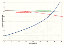
But it doesn't make a great deal of difference. I have added the system curve in green to the original plot showing the flowrate when the Bernoulli and entrance effects are ignored. The pump curve is quite steep in this region and the suction flowrate only increases to about 340 lb/h.


3 in Hg means 1.47 psi vacuum which is 14.7-1.47=13.23 psia suction pressure.

From the give curve, it appears that suction capacity will be around 220 lb/h.

But these parameters will be valid for a particular motive air pressure, which will be mentioned in the ejector specification.

This is a very relevant observation. It seems that the test that gave the 3"Hg vacuum was performed with zero suction flow, but the curve shows that at zero flow the suction pressure should be 12.0 psia or 5.5"Hg of vaccum. It seems that the exhauster is under-performing and the actual motive air pressure needs to be checked against the specification.

2400170 CURVE s2.gif
 
Last edited:
I was not looking at the curve correctly. Now I understand that the no-flow condition is at a dead-head condition, and maximum flow at roughly ambient happens because there is no resistance to the flow. Thank you. Yes, this curve is not quite accurate for our conditions.

From the manufacturer of the Exhauster (eductor): Your jet was designed for a much higher suction pressure (14.3 psia), so the attainable vacuum is different. Approximate curve is attached.

Unfortunately that is all we have been provided by the manufacturer, and I don't know what the offset would be for our conditions. I'll proceed as if this curve is close enough to get to an understanding and then will make any adjustments if i get a better curve from them.
 
I've avoided this post for a while, but I don't think anyone is going to get anywhere until you start from known pressures. The key missing bit of data is what is the pressure in this mysterious furnace? So until you either know that or can work out from a known pressure (i.e. atmospheric) what the total losses and gains are from air inlet into the furnace for different air flows, you're not going to be able to get any sensible answers with which to balance flow and pressure difference from the eductor. IMHO.

So can you sketch up the air flow from air inlet at atmospheric through the burners / furnace etc up to the point where the very hot air is being taken out. As its only a 1 1/2" pipe the air flow must be pretty low and this furnace thing about the size of a snack box?
Ours is an R&D facility. This is a full scale furnace as used in refineries. Roughly 10 x 8 x 15 ft^3 in the radiant section, which is where we've tapped through the roof for this particular test. The 1-1/2" pipe is part of a test piece only.

I mentioned earlier that there is a slight negative pressure in the furnace of 1" H2O, maintained by balancing inlet and outlet fans via VFD. We measure this pressure very near where we mounted the Exhauster.
 
I do not agree with the analogy of using the same concept as a pump curve and system curve and finding the intersection. My understanding under that analogy the system curve drawn in red (or green) is the pressure loss in the pipe at given flow. So at 14.66 psia suction pressure (pressure in the vessel to be exhausted) a curve of pressure (psia) versus flow is determined which would be the pressure measured at the "top of the pipe" which is basically the flange connection of the ejector. Then it is assumed that the flow curve of the ejector in blue is as curve that gives the pressure at the ejector versus the flow so that where the curves intersect gives you the resulting flow like a pump/system curve intersection. So in this case you are saying that a flow of 320 lbs/hr in the ejector suction corresponds to a pressure inside the pipe at the inlet to the ejector of about 14.2 psia.

The way I interpret the curve is that it gives the suction flow developed in the ejector based on a suction pressure in the tank that you are taking exhaust from when there is no additional pipe added to the ejector. Therefore if the tank pressure is 14.66 psia the flow will be about 350 lbs/hr if the ejector was bolted directly to the tank flange with no additional pipe added, as I assume this is how the device was flow tested at the shop to develop the curve to begin with. If you do add pipe then that pipe straight length needs to be taken into account by adding the pressure drop to the suction pressure shown on the curve to get the actual flow.

For instance in this case with suction pressure of 14.66 psia the corresponding suction flow would be about 350 lbs/sec with no added pipe. However with 3 feet of added pipe the curve would need to be adjusted as follows:

Determine loss in 3 feet of pipe at 350 lbs/sec = 0.16 psi (based on Spitzglass equation)
Subtract from actual suction pressure = 14.66 - 0.16 = 14.5 psia
Find corresponding flow on curve = 340 lbs/hr approx.
Since 340 lbs/sec is approximately same as 350 lbs/sec then pressure drop at 340 lbs/sec is about 0.16 psi so no more iteration required.

Furthermore I believe what the curve indicates is that there will be no flow if the pressure in the exhausted tank is 12 psia since 12 psia is the maximum suction pressure capable of being produced by the ejector. So at design compressor flowrate and discharge pressure in the main flow line, the pressure inside the ejector produces a maximum vacuum of 14.7-12=2.7 psi vacuum. Since the compressor operates, I assume, at only one fixed discharge pressure and flow, the minimum pressure of 2.7 psi vacuum (12.0 psia) always exists in the ejector when in operation as designed.
 
Last edited:
The cost of labour spent by engineers on this thread has now well exceeded the cost of this hot wire anemometer type flowmeter, and we are still nowhere near a reasonable estimate of this flow.
 
The cost of labour spent by engineers on this thread has now well exceeded the cost of this hot wire anemometer type flowmeter, and we are still nowhere near a reasonable estimate of this flow.
I accidentally hit like when I meant to hit reply. I actually don't like it. While it may be true looking at it from a bean counter perspective, it is a learning opportunity for an engineer. It's been a good use of my time learning about a discipline I had no experience with that hopefully will be of use again in the future. Hopefully others will have similar thoughts.

I said that this test had already been performed and will not be repeated, so unless you can hook me up with a time machine, measuring the flow with a hot wire aneometer ain't happening.
 
I missed the 1" WC data in the furnaces, but now agree with snickster. The constraints in terms of volume is really the eductor.

So yes there is a pressure drop in the tubing, but even at max flow through the eductor is really quite small in relation to the negative pressure available.

If you connected two eductors then you would have nearly double the flow.

It's all about finding the constraint in the system which in this case is the eductor. IMHO.
 
I do not agree with the analogy of using the same concept as a pump curve and system curve and finding the intersection.

Whether we are looking at a centrifugal pump curve together with its system curve, or as in this case where we are looking at an ejector curve and a system curve all they are is a graphical technique of solving two simultaneous equations. I have used this graphical technique and you have done it algebraically - and we both come to a flow of 340 lb/h and a suction pressure at the ejector of 14.5 psia.

So if you don't like the analogy to the centrifugal pump situation then that is fine - just think of it as a graphical technique of solving the same equations that you did. In fact it is always reassuring when two different techniques give the same (or very similar) results.
 
The device referred to is commonly called an "eductor", many designs are available on line with calculation procedures. I would first refer to Perry's handbook, but if not there, then an online search under the tag eductor should result in the design method and also vendors .
 
Thank you everyone for the input. It's been a good education for me, and is much appreciated.
 

Part and Inventory Search

Sponsor