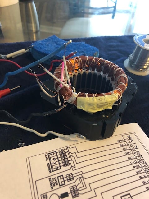
So, I have a 3 wire motor with capacitor which runs clockwise. I am trying to rewire it to run CCW. From what I understand, I need to flip the connections on the starter windings, which should make it run the other direction. However what I found when I opened up the motor is confusing me. I expected to find 2 coils (4 leads, starter and main coil), with the ends of both coils tied together on the neutral wire. What I found instead is 6 wires coming off of the coils (the wire sizes are similar, so its hard to figure which is which by eye). These are the wire details...
Outside the motor:
RED/ORG - Capacitor Wire plugs
BLU/WHT/BLK - Motor power wire plug
Inside the motor:
Red goes to 1 coil end.
ORG/BLK go to 1 coil end
BLU goes to 1 coil end
WHT goes to 2 coil ends tied together and a thermal fuse. Other end of thermal fuse goes to another coil end
BLU - WHT - 6.1 ohms
BLK - WHT - 15.2 ohm
BLU - BLK - 21.0 ohm
RED - WHT - 25.0 ohms
So from this I believe that BLK-WHT would be the starter windings. And BLU-WHT would be the main windings. RED-WHT confuses me
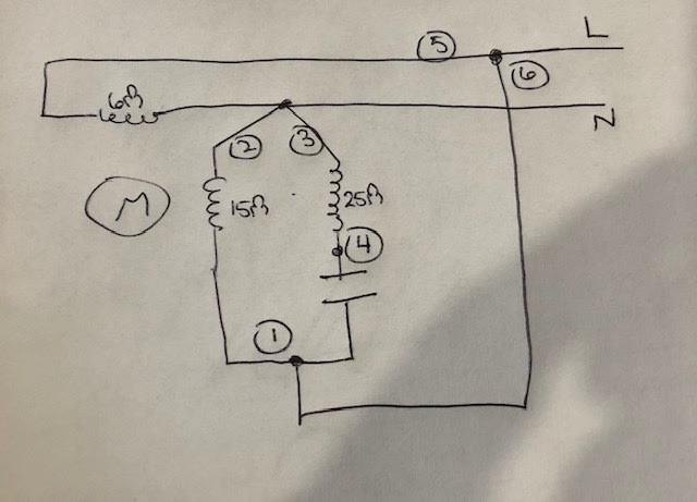
I disconnected the 6 wires and I am getting 15.2 ohms on 2 of the leads, and I get 6.1 ohms on another 2 of the leads. So that should be my starter and main coils.
With the last 2 leads I get 25.0 ohms
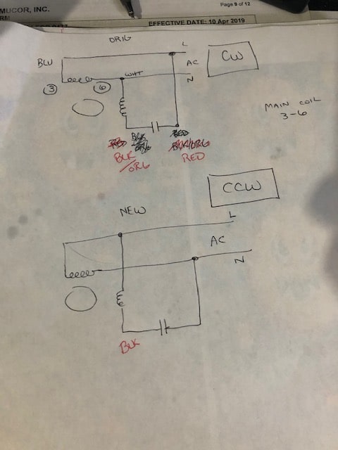
What I don't understand is why does it appear that there are 3 separate coils on the motor? I tried just flipping the two leads that go to the starter coil, but all the motor does is hum when it's energized. I feel like I'm missing something with the 3rd coil (if that's what I'm seeing) that the red capacitor lead goes to. This was the diagram that I was trying to use (colors indicated may be incorrect). top is what I thought the original config would be, bottom is to reverse the motor.
Could the capacitor leads be hooked up across a 3rd coil and my diagram is wrong? Can anyone point me in the right direction for what I'm trying to do?
Thanks!!


