Eng-Tips is the largest engineering community on the Internet

Intelligent Work Forums for Engineering Professionals

  • Congratulations waross on being selected by the Tek-Tips community for having the most helpful posts in the forums last week. Way to Go!

Trying to understand design features of sewage pump

Status
Not open for further replies.

jimhokie

Mechanical
Feb 16, 2005
50
0
0
US
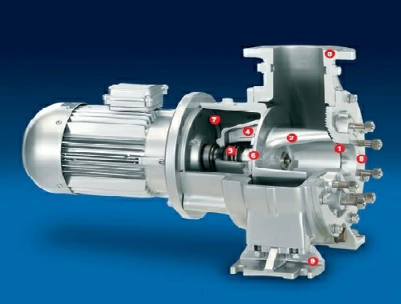
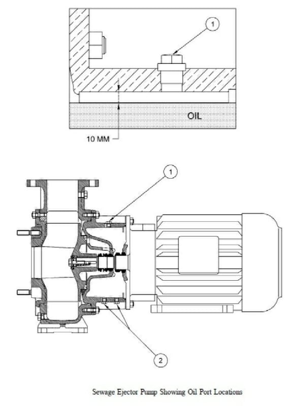
We have had a high failure rate of sewage pump seals in a fairly new installation, which then leaks black water into the motor bearing with predictable results. The pump model is UNIVERS-A by Herborner. There are a number of system issues I believe are contributing to the failure rate, but first, I'm trying to fully understand the design principles of this sewage pump. It has an oil-filled intermediate cavity between the process fluid and the motor, with seals at each end sealing the shaft entry points. As I understand it, this oil volume provides a buffer from blackwater leaking directly into the pump environment upon a seal failure. On the process fluid side, the seal is exposed to the blackwater and all debris entrained in it, with no flush fluid provision. This seems like a major seal no-no to me. The oil cavity is filled almost completely full, with a small air space at the top, then plugged. So it is at ambient pressure, except I presume some pressure will develop due to heat-up during operation. There is no means to maintain pressure by oil replenishment. When the primary seal fails, blackwater leaks into the oil volume, and when the oil seal fails, the oil/blackwater leak into the motor bearing. Both seals are failing at a high rate on multiple pumps.

So, is the oil also supposed to be the primary lubricant on the main water seal such that it precludes blackwater from entering the seal? If so, how does this work without a pressurized oil side? There is a flow path of process fluid to the seal from near the impeller edge, so it seems that the higher pressure side of the seal is the blackwater and not the oil.

I'm very familiar with other clean water centrifugal pumps, but this is a strange bird to me. Any information will be greatly appreciated.
 
Replies continue below

Recommended for you

A sectional drawing or pump details would help.

The Herborner website seems to need registration and I can't be bothered to do this, but looks like it has lots of information.

Remember - More details = better answers
Also: If you get a response it's polite to respond to it.
 
jimhokie; Please use the
ice_screenshot_20160718-141231_bg3wec.png
above to directly post your pictures as this saves everyone from Clicking Hell.

Herborner_pump_1_oiemtd.jpg


Herborner_pump_2_ydxzqs.jpg


Keith Cress
kcress -
 
Have you involved the agent / manufacturer in the failures or a knowledgeable seal engineer.

This design is nothing special or a new idea.

A good chance it's an application or hydrauluc problem, a missed matched pump to the duty. Full pump spec. and good detail on the specified and actual onsite pump output might give a lead into the problem.

It is a capital mistake to theorise before one has data. Insensibly one begins to twist facts to suit theories, instead of theories to suit facts. (Sherlock Holmes - A Scandal in Bohemia.)
 
What is the seal material and design?

It doesn't look like there is much of a seal housing, but there isn't any real information on where the sliding surfaces are or how robust that housing is or whether the pump is being operated in line with the operating requirements.

To have the motor hung out the side like that also adds a lot of stress to the unit.

However as artisi says this is a common looking design so maybe something has changed in the design or seal material or they are being operated outside their design envelope.


Remember - More details = better answers
Also: If you get a response it's polite to respond to it.
 
Thanks for all the responses. I'll try to address all the follow up questions, but let me give more background on my situation. I've been asked to assist another group who owns the system these pumps are installed in based on my more extensive pump background than the system owners. Unfortunately, my pump background is primarily with pumps pumping clean water, so this sewage pump and its oil-filled cavity are a first for me, but I figure this must be a standard feature in sewage pump designs. So that's mostly what I'm trying to understand as it relates to how the seals are supposed to work in this pump.

LittleInch, I'm awaiting details on the seal materials, which have been revised...I was told one material in the motor flange seal was compatible with oil, but not blackwater once oil cavity was contaminated. But that has apparently been addressed, but is not preventing early failures. The catalog cut does not show the motor to be supported, but it is, using the motor feet holes shown in the cutaway sketch.

To answer Artisi's question, long story, but the pump supplier has become unresponsive to us, so they are not available to answer my specific questions on nuances of the pump/oil/seal design features. I believe the pump is correctly matched as far as the head/flow curve to the system. That said, this seems to be a textbook case of some other pump no-no's...water hammer in the pump discharge upon start-up, possibly high environmental vibration, and excessive connected pipe loading being among the worst. So I'm pretty sure WHY the seals are failing so quickly given a handful of likely candidates, but need to better understand how the seal lubrication is supposed to work assuming the other system problems are resolved.

This is a commercial design, but in looking at MIL-P-24475, which is a military spec for sewage pumps, this spec requires the water-side seal to have a clean water flush, and requires the oil cavity to be pressurized. Neither of these requirements are met on this pump. This design doesn't even seem to have a means of providing a clean water flush, but could have a pressurized oil cavity via the fill plug. Does this mean that a pressurized oil cavity is intended to provide an outward flow of oil through the water-side seal faces, thus preventing debris in the blackwater from affecting the seal faces and therefore negating the need for a seal flush?? Also, as the water seal degrades, any leakage would be oil into the process fluid vice blackwater into the oil cavity, and upon failure of the motor flange seal, oil/blackwater into the motor bearing.

Can anyone familiar with sewage pumps clarify this pump's design feature intent?
 
I would assume this being a sewage pump, the seal design would have been researched and refined since initial concept.
From the drawings it is impossible to see the seal arrangement - do have a more detailed drawing, however there are thousands, probably hundreds of thousands of pumps including submersible pumps running world wide of similar arrangement on sewage and tougher applications with no water flush.
As you said the seal is or should be arranged for the oil to move from the reservoir outwards to lubricate the seal faces.

1. Are you using OEM seals or identical seals - wrong seal selection could / will lead to failure?
2. Is the pumped flow continuous, variable,or intermittent - if variable / intermittent the impeller could be shuttling axially causing the unloading / loading of the seal faces?
3. Are there times when the inflow is low but the pumps continue to run on low flow?

Just for interest, are there pump-out vanes on the back of the impeller back shroud,or balance holes through the back shroud?

I would be looking into it as an initial hydraulic application problem - seal failure is just a by-product.

Good descriptive post/s on your part, not like many others that require a crystal ball or guess work trying to see what the story is about.

Edit: is the pump operating on suction lift or positive inlet head?


It is a capital mistake to theorise before one has data. Insensibly one begins to twist facts to suit theories, instead of theories to suit facts. (Sherlock Holmes - A Scandal in Bohemia.)
 
Artisi, thanks for the detailed response. Yes, I would presume the OEM seals would have been designed for the service, and we are using replacement OEM seals, but apparently there has been some material changes made already to address corrosion found in earlier failures. And I agree that with so many similar pumps in service, the high failure rate we are experiencing is more likely a result of our specific installation and operational problems. I mainly wanted a better understanding of how this pump is supposed to work in order to better assess if it is not a good pump for our system.

The operation is intermittent...the pumps cycle on and off based on tank level indication, and due to poor piping design, are subject to water hammer in the discharge pipe upon start-up. I am recommending the bad piping design be corrected as a minimum.

To answer your other question, I don't believe there are pump-out vanes on the back of the impeller back shroud. It's not clear to me that there is a complete flow path in and out of the seal area. It appears to me there is an inlet path into the seal area, but not separate flow path out...seems like a dead end. But again, this design must be proven in thousands of other sewage applications.

I suspect our problems are mostly attributable to known factors such as water hammer in the discharge pump during start-up, and high environmental vibration. Fibers (mop threads, feminine hygiene products, etc.) have been found wrapped around some failed seal compression springs, which conceivably distorted the spring, affecting the seal face alignment, but this falls under the category of something any sewage system should have to deal with. The impeller does have macerator teeth, which apparently aren't designed for, or effective against, string fragments. Other suspected problems are excessive connected pipe strain distorting the pump casing, and poor seal replacement practice since replacement seals are failing more quickly than the originals. There are too many smoking guns here to know what the real problem is...perhaps a combination. I'm just trying to determine if we have the right pump if all other contributors are eliminated. I've seen something called a tornado pump that sounds like it would better handle various solids that get flushed.
 
At a loss to add much more, only a couple of things to look at:

1. Has this been a problem from initial start-up or has it developed as the pumps internals have deteriorated - increasing clearances of wear rings and impeller back plate / housing?
2. Investigate a seal arrangement that doesn't have springs etc exposed to the pumped liquor.
3. can a macerator be fitted prior to the pump inlet or to the incoming pipework?
4. does the pump operate for a long time at low flow?

The drawing posted are not really clear to show the internal arrangement of the impeller / casing interface so difficult to comment on this area.


It is a capital mistake to theorise before one has data. Insensibly one begins to twist facts to suit theories, instead of theories to suit facts. (Sherlock Holmes - A Scandal in Bohemia.)
 
Check your suction piping. If there are irregularities in the suction hydraulics, that may radially load the pump. Did you check the influent for unusually high solids content? That can also cause radial loading on these pumps. With higher radial loads, the shaft deflection at the mechanical seal may exceed 2 mils (0.002 inches) which they are usually designed for. At higher deflections, seals fail quickly.
 
Status
Not open for further replies.
Back
Top