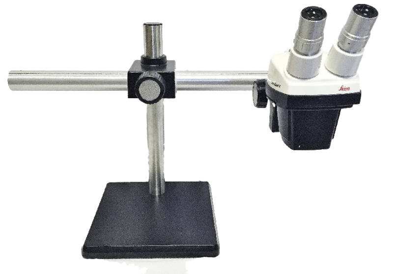
> The attached image shows the setup. The step force was applied by adding 50ml to an empty milk container hanging on a string, run through a small pulley to apply a torque to the monitor arm.
> A bump is best represented by an impulse, which is equivalent to a broad band noise input. I don't have a broad band movement generator so I use an impulse (a bump). The really nice thing about an impulse is that it is equivalent to a unity function.
A bump test or step test would both be good ways to characterize a linear system AS LONG AS you record and properly analyse the dynamic response, but I'm not convinced that what you did. First imagine that you were reading the position of the dial indicator in steady state after the system comes to rest, then you are seeing the static response to a force at zero frequency (dc) rather than the dynamic response to the component of the ac excitation that is at the natural frequency, and it would not be a good represntation of the movement at the natural frequency. I don't think that's what you did, but I bring it up because I think it's intuitive to see that wouldn't work and it sets the stage for what comes next. I think what you actually did was to try to capture the peak movement during repeated drops from the same height... even in that case the peak response is likely still heavily influenced by the dc component of your applied dynamic force. It's unlikely (unless you're just lucky) that peak response would represent the modeshape of the first resonant frequency of interest. If I misunderstood your test or the way in which you think it will represent the modeshape of interest, please clarify.
> This is a microscope so in use, it is going to be knocked by the user, or the table may be bumped....;So a TMD filters the input noise. It changes the frequency response of the monitor stand ( the output) and adds damping to rapidly stabilize the image. That's why I am using a TMD.
Again undamped TMD is generally not a good solution for broadband excitation. All it does is shift your resonant frequency slightly (in both directions, replaces SDOF single resonant frequency with 2DOF two resonant frequencies on either side of original resonant requency), so broadband will likely still excite the new frequencies.
Stiffening can sometimes be a good solution even for broadband force excitation because
1 - all real-world broadband has an upper frequency limit. If you can stiffen to move the first resonant frequency above that limit, then you will reduce vibration.
2- The excitation may be quasi broadband... maybe it starts out broadband elsewhere in the room, but what gets through to your tabletop depends on resonant transmission frequency of an intermediate component. Flexible systems have higher density of modes at low frequencies than stiff systems. Even if you are not successful in moving the first resonant frequency above all excitation, the odds of having a resonant frequency land near an strong exciting frequency are still lower in a stiff system than in a flexible system due to the difference in density of resonant frequencies (how closely they clump together in frequency).
3 - Let's say the broadband is effectively ideal to infinite frequency (constant force as a function of frequency). Assuming your system is a SDOF with constant damping, then increasing stiffness will still reduce peak displacement because the new resonant frequency is higher and peak displacement magnitude... is |Force|/(c*w) which is inversely proportional to frequency. Aslo the entire X(w)/F(w) transfer function curve everywhere to the left of the resonant frequency decreases in magnitude as the stiffness increases.
I'm still thinking a c-clamp is well worth your time to try (btw even if we believe you have properly captured the modeshape of interest, then it still suggests that clamping of the plate will reduce or at least alter that particular mode). I don't know your situation... I'm curious how much time/effort does it take to see if you have fixed the problem after a trial fix?
EDIT - I see now that you've got a C-clamp in there now in the test photo (sorry, that's a duhhh moment on my part). So maybe my last several paragraphs are irrelevant (I changed them to grey). Did the c-clamp it change the vibration experienced by the microscope?
I'm not a vib expert but undamped dynamic absorbers (TMD) is something I have worked on.
Attached is a presentation I gave at an industry group regarding successful use of a dynamic absorber solution at our plant (for a fixed frequency excitation). Slide 14 gives an example qualtative view of the before/after transfer function. Slide 17 tells you how far the two new natural frequencies are from the original natural frequency. The higher the attached mass in relation to the original SDOF model mass, the more the separation from the original frequency. If you don't get much separation the likelihood of solving the problem is low. Even if you do get separation by attaching a relatively large mass, for broadband excitation it's still questionable.
=====================================
(2B)+(2B)' ?