Eng-Tips is the largest engineering community on the Internet

Intelligent Work Forums for Engineering Professionals

Turbine balancing - updated question

Status
Not open for further replies.

dynaman

New member
Dec 17, 2011
75
0
0
AU
Hi all

I'm currently balancing micro-turbine rotors using 2 plane balancing method. ISO1940 G2.5 requires a quality balance limit of 0.033mm.gram per bearing location in my case (100,000rpm), which I'm finding near impossible. Is ISO1940 limits a bit of an overkill? The best I can physically achieve is an order of magnitude higher (0.33mm.gram).

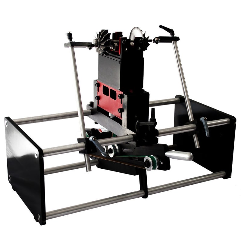
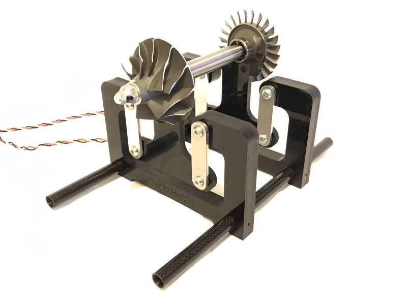
I have updated with an image similar to what I'm using. It appears that there is always some residual mechanical vibes present. The bearings have been changed to quality Japanese bearings which have little play in them. Also the balance cradle has some play along the shaft axis so the cradle isn't too over-constrained. The turbine is driven by compressed air at around 3000 RPM. I find this works well enough to see vibes in the system.

IMG_1248_mh4vh1.jpg
.

thanks

Dynaman.
 
Replies continue below

Recommended for you

Hi Greg

Its a soft bearing balancing cradle. Its mean't to be flexible enough to allow the rotating mass to move freely like the one shown in the image.

In the commercial system, I noticed that the rotor has axial stops, I wonder if that makes a difference?

thanks

DM

typical_support_u45pqf.jpg

s-l1600_zdvwcs.jpg
 
What is your balancing speed?
Do you have the option of an underslung micro flat belt drive?

Are you balancing in the service bearings as the image suggests?
Are the outer races just resting in Vees machined in the T plates?

Which bearings were changed to "quality Japanese bearings" ?

Is the limit sensitivity, or noisy signal, or time varying "unbalance" ?

What is sensing the vibration?
What averaging capabilites does the processor software have ?
Can you capture and provide a time wave form of what the processor is seeing?

The first thing I'd do is change from pivots and links to thin reed/leaf springs.
Do you have a cross section of the micro-turbine General Arrangement?
Might need to axially preload the rotor service bearings to get them to run true and quiet. That would require a "housing" common to both bearings.

I foresee non repeatability issues after the rotor leave the balance machine when the rotors are removed then re-assembled for final assembly.
 
I thought ISO 1940 for "rigid rotors" (in other words, the first flexible rotor critical sufficiently far above operating speed).

I don't think your machine will act like a rigid rotor, so I'm not sure ISO 1940 applies (and you probably can't get away with low speed 2 plane balance)


=====================================
(2B)+(2B)' ?
 
Hi guys

Thanks for your help. This is what I know so far;

* Balancing speed is 3000 RPM, yes operational speed is 100k RPM
* Bearings in the attached image have been replaced by quality Japanese close cage bearings that have virtually no play in the inner race.
* Noise levels in the system are much lower than the residual balance signal I see. Still looks sinusoidal but with multiple harmonic noise in the mix.
* Vibration is being sensed by MEMS accelerometers 100mV/g.
* I tried leaf springs originally. Worked well enough but found bearing pivot cradle to be much more sensitive and responsive to mass changes.
* Reloading bearings crossed my mind but commercial units run the rotors freely without preload.
* Process is repeatable if rotor is rebalanced in same configuration. Installing in engine requires new balance process.
* All mass components on the rotor are rigidly fixed. The size of the shaft compared to span appears to be reasonably rigid. Haven’t heard any reports of resonance during operation of these engines.
* balance at 100k RPM? ISO 1940 only provides residual unbalance limit at operational RPM. That residual can be determined at any reasonable speed if the solution is linear.

I'm starting to think now that the axial motion needs restraining to a degree, especially with coupling effects this could be causing secondary motion on the sway arms. Will test and feedback results to the forum.

thanks

DM


dynaman said:
Rotor is rigid, can't see any flexibility in that shaft what so ever.
That's not very convincing. I'm going to assume you're unfamiliar with the particular balancing terminology: "rigid rotor". I apologize if I'm mistaken.

The definition of "rigid rotor" I'm familiar with is that rotor doesn't flex at operating speed.

One way to assure rotor is rigid is to ensure the first flexible rotor critical is far enough above operating speed (maybe 20% above). If this condition is not met, then flexible rotor modes may influence the rotor's operating deflection shape, in which case the rotor flexes at operating speed.

If rotor flexes at operating speed then 2 plane balancing at lower speed (where the same flexing doesn't occur) generally isn't appropriate, and iso 1940 doesn't apply.

It's hard for me to imagine that a rotor at this high speed is rigid.

Do you know at what speed the first flexible rotor critical occurs?...or alternately do you know the operating deflection shape at running speed?

=====================================
(2B)+(2B)' ?
 
The MEMS accelerometer may not have a low enough threshold, so consider upgrading to piezo accelerometer. Background vibrations may be a factor, so measure vibrations with machine off. Consider using a narrow filter and synchronous averaging.

"Why would I balance at 100k RPM? ISO 1940 only provides residual unbalance limit at operational RPM. That residual can be determined at any reasonable speed if the solution is linear." Not likely true for this situation.

As Pete says the ISO 1940 procedure is not suitable for this rotor. There is anther procedure for low speed balance of a high speed flexible rotor, that requires each component be balanced during assembly. You may get lucky with the procedure you are following, but have a basket ready to pick up the pieces when raising speed to 100k rpm!

Walt
 
Low noise MEMS are available almost to the same noise levels as piezos. In my case the residual waveform is much higher than signal noise, hence the issue is predominantly mechanical. If ISO 1940 isn't applicable, then what is? How do the commercial balancers such as the one shown above achieve this? Ther are many around that look like that.
 
Make sure the balancing machine is on a rigid base. Try a different (higher or lower) speed to avoid resonant behavior. Look up some references:

Flexible Rotor Balancing

21.120.40 
Balancing and balancing machines

From <
ISO 21940-12:2016
Mechanical vibration — Rotor balancing — Part 12: Procedures and tolerances for rotors with flexible behaviour

From <

Search: balancing of flexible rotors

Walt
 
Hi all

Well conducted some further testing today by restraining motion along the shaft axis. I noticed that the waveforms improved much more and I was able to get closer to my target quality limit 0.04 to 0.06 mm.gram. As mentioned by Greg the flexibility in the sway bars makes a difference. Because I'm driving the turbine using compressed air it tends to oscillate somewhat (out of plane), so after taking out the unwanted motion, things improved.

cheers

DM

 
Seems like you are still focusing on 2-plane low speed balance with ISO 1940. I don't work with high speed machines like you've got, but to me it sounds dangerous to just pretend it's rigid and hope for the best. i hope you have some serious safety precautions / monitoring in mind when you (or your customer) take the machine up to 100krpm. Just my two cents fwiw.

=====================================
(2B)+(2B)' ?
 
Status
Not open for further replies.
Back
Top