Continue to Site

Eng-Tips is the largest engineering community on the Internet

Intelligent Work Forums for Engineering Professionals

  • Congratulations GregLocock on being selected by the Eng-Tips community for having the most helpful posts in the forums last week. Way to Go!

Turning a system by 90º part 2 2

Status
Not open for further replies.

drodrig

Mechanical
Mar 28, 2013
260
thread404-468702

Hi,

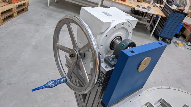
We have already build the turning device. The post where I asked is closed


I just wanted to share some pictures and say thanks to everybody
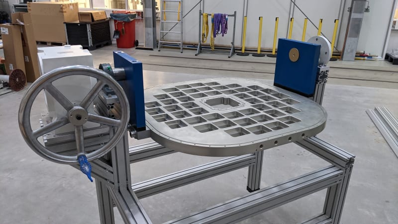
PXL_20210929_080849049_bxq6eg.jpg


PXL_20210929_080856427_yeql9j.jpg


cheers,
 
Replies continue below

Recommended for you

desertfox said:
We always had shims to adjust the height of bearing housings and geared motors

I don't know what shims are, but OP uses aluminum extrusions, meaning the height of the gearbox can be easily adjusted, i.e. exactly aligned with the shaft.
You mount the shaft, you mount the gearbox on a shaft, and then you just put the structure underneath the gearbox. You let the shaft and gearbox dictate where the supporting structure will be, not the other way around.
 
The vertical alignment is not a problem because we have the aluminum profiles that were cut at the same length. We can adjust the whole supporting frame (4 feet at the ground).

The problem is the horizontal alignment.

desertfox, you wrote:
we built the frames up and had bearing housing pockets machined on both sides of the frame simultaneously to ensure horizontal alignment
Could you elaborate more that? do you have some pictures or sketches?

Scuka,
I understand shims are parts to move up or down the bearing (like a wedge, or screws)
Your assembly procedure seems logical. But the gearbox is heavy and it is not easy to inset the shaft into the gearbox hole (we need to use clamps). Since the bearing block can rotate it is not easy to align the first shaft
 
If you had spherical bearings that were allowed to work on both ends you'd be o.k. with some misalignment. Problem is that the spherical bearing located next to the rigidly mounted gearbox output shaft isn't able to wobble. If you have slop in the output shaft it may be able to move a bit but that's really not the way to go.
 
^ that's a good point.

Bearings compensate for angular misalignment, but if they're not at 0° (which they never are, that's why these bearings are used in the first place), the end of the shaft wobbles. If there's a gearbox, it constrains the wobble, which might create problematic forces one didn't expect.
 
Hi drodrig

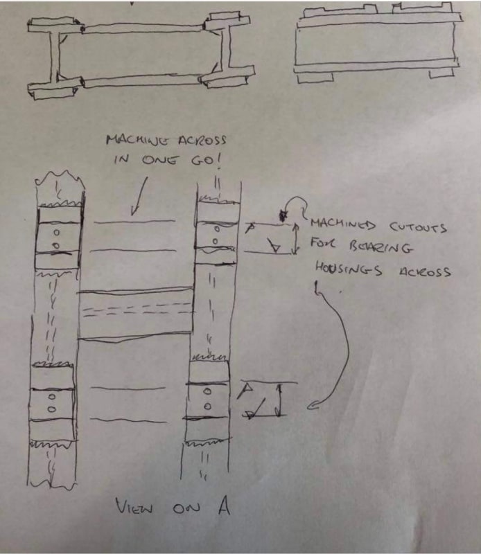
See sketch, I have a 'I' beam right hand and left hand frame joined by an 'I' beam running horizontally across, plates are also welded to the top of the'I' beam and the whole thing is mounted in a machine and the welded plates on top of the 'I' beams are machined across in one go to ensure horizontal alignment.
frame_machining_h4msyj.jpg


“Do not worry about your problems with mathematics, I assure you mine are far greater.” Albert Einstein
 
I'm not sure a machined frame would help - pillow block bearings use over-sized clearance holes for the 2 mounting bolts. You'd still have a problem in the horizontal plane.
 
I'd modify the blue bracket next to the gearbox to accommodate a spherical bearing inside it and get rid of the pillow block support on that end. Then maybe something like a "lathe dog" to transfer the torque to the bracket.

Or use a flange mount pillow block mounted to the left blue bracket (with a lathe dog):


We also used to machine the ends of the pillow block and make a machined fit with the pocket in the frame, so a tight clearance fit, the hole being oversized wouldn't matter then.

“Do not worry about your problems with mathematics, I assure you mine are far greater.” Albert Einstein
 
The bearing in the Two-Bolt Flange looks very nice. Easy to align.

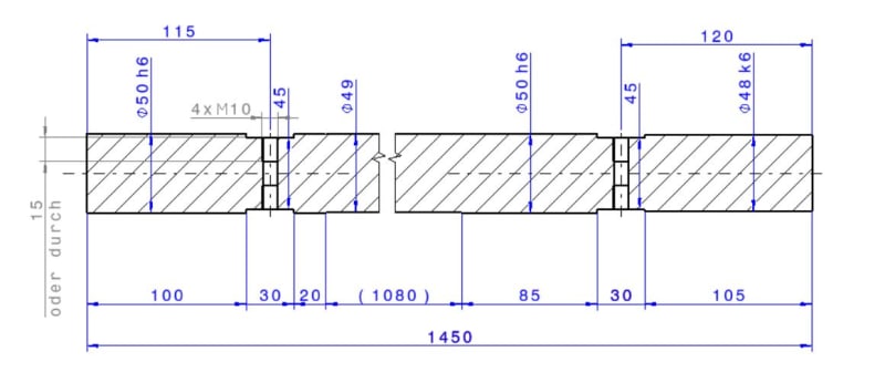
What about making a long bar (1450mm - 4.75 feet) sticking it in the gearbox and then position the bearings. Even with the block bearings

I have to check with our workshop if they able to produce such accurate rod. Maybe using different sections connected by dowel pins

long-shaft_foem7t.jpg
 
I think a long shaft would work well for your application. There will be slop in the 3 shaft/bore interfaces and deflection of the bar. Those you can calculate to make sure alignment error is within acceptable limits.
 
Status
Not open for further replies.

Part and Inventory Search

Sponsor