Eng-Tips is the largest engineering community on the Internet

Intelligent Work Forums for Engineering Professionals

Turning on & off a motor using PWM from a remote control. 2

Status
Not open for further replies.

mingki

Chemical
Mar 4, 2011
52
0
0
KR
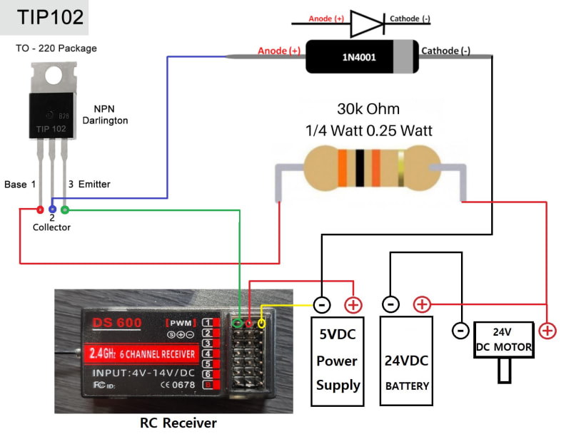
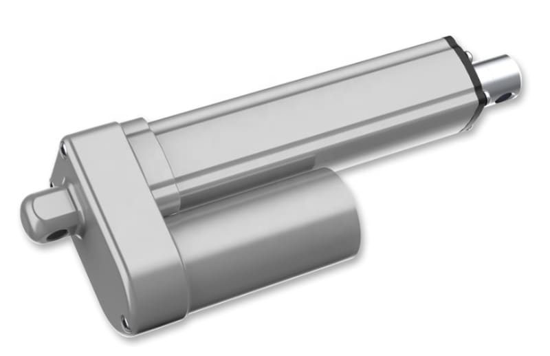
Hi, I am trying to get my 24V(70W) motor turn on and off using my remote controller.
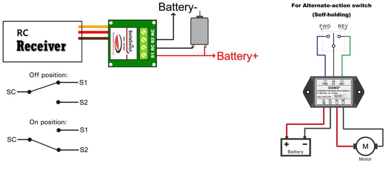
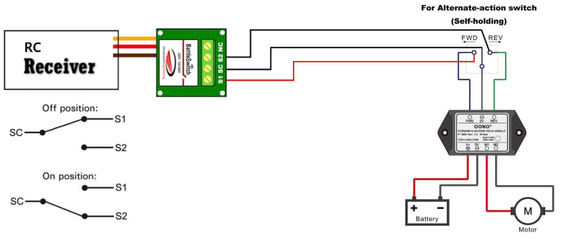
This remote controller puts out PWM from its receiver so I want to be able to control on & off action of my motor using a remote control.
Is there a simple tutorial or circuit to follow?
Thank you.
 
Replies continue below

Recommended for you

The rest of us can't read your mind. What's the motor, what's the "remote", what's the "receiver"?

Be specific. Manufacturer, model number, link to specifications, etc. "24 volts" ... AC? DC?

As an aside, PWM usually isn't used to turn things completely on or off, it's normally for varying the supplied power in order to vary speed/brightness/heat output etc. But it has to be the right type of device being controlled to avoid having the magic smoke come out. An AC motor isn't going to be happy about being fed PWM.
 
My motor is operated on 24V.
Remote controller alone can not power the motor so I came up with a circuit using TIP102 transistor and 1N4001 diode.
TIP_as_a_switch_to_turn_motor_on_off_lr7vah.jpg

Could you review my circuit and tell me whether it is workable?
 
Buy something like this:
Explanation:

Since the PWM will never be 0% or 100% as long as the transmitter is on** and is multiplexed with the PWM of other channels it won't ever be fully on or fully off. Better put a huge heatsink on that transistor if it ever sees motor current - which looks like it might let the smoke out of the receiver, though with that large resistor not enough current will flow through the motor to make any difference.

R/C Motor controllers are cheap and take care of all these problems, though the 24V might be a problem. Most will allow the motor battery to power the receiver, eliminating the extra battery. As mentioned above a relay can turn the motor on and off.

The better home-built circuit is a 555 chip wired in a bistable configuration with the trigger set at some duration of the PWM pulse. The output of the chip can be set to run for longer than the refresh rate so it will effectively latch as long as a pulse of sufficient length comes along to refresh the state. As flexible as the 555 is a timing solution is possible. The output from the chip can then pull down an NPN transistor that in turn operates a relay to handle the 24V motor. See for how to use the 555. There is a circuit shown in by Forrest Mims, page 158. (Mims Circuit Scrapbook V.II)

**I don't know what the spread spectrum channel hopping digital systems do - in the old analog ones the pulses out of the receiver were initiated on a one-for-one basis in the transmitter. When the transmitter was off there would be no pulse train for the receiver and the servos would have no pulse to match an error feedback against. Maybe the receivers now just maintain the pulse train they were last commanded to do? The main thing is that the time between pulses can vary - but servos only care and can measure where they are during the duration of each pulse.

said:
RC servo signals are not the same as PWM used to drive motors. The RC signal is a 50Hz to 100Hz pulse train with a pulse width that ranges from a minimum 1mS to a maximum of 2mS with 1.5mS decoding to a center position on an RC servo.


A PWM signal to a motor is usually 20kHz with a duty cycle that ranges from 0% to 100%; a 50% duty cycle causes the motor to be stopped.

To get what you need:

1. Detect the rising edge of the RC pulse.
2. If rising edge is detected, wait 1mS
3. Reset an 8-bit register
4. If pulse signal is still a '1', increment the register, else go to step 7
5. Wait 4uS
6. Go to step 4
7. If register has overflowed, go to FAULT
8. Conversion complete. copy register to PWM register
9. Go back to step 1

This is a very rough description. The 'wait 4uS' step scales the 8-bit register to accumulate a maximum of 255 counts in a 1mS period. A small PIC or similar MCU is perfect for this application.
 
3DDave
Thank you very much for your insight.
I will try to test my motor using the battleswitch as you mentioned.
I think this thing is just what I need to trigger the on and off function of my motor.
My 24VDC motor is a linear motor like this.
Linear_actuator_dsirxl.jpg

I need to be able to control the clock & counter clockwise motion of this motor so that I can have open and close function of my door.
Could you tell me how to set up this mechanism using battleswitch?
 
The schematic shown has a wire connecting battery positive to one terminal of the motor and another connecting to the other terminal. The motor will run full speed in whatever direction that implies until it reaches a mechanical stop, and then let the smoke out. No current will flow through the resistor because there's no escape path for it that leads to the other side of the circuit. All the other stuff in the circuit is decoration.

Normally there will be a forward relay and a reverse relay, and limit switches to break the forward control circuit before it hits the forward mechanical limit and break the reverse control circuit before it hits the reverse mechanical limit, and careful thought put into preventing something bad from happening if you try to energise forward and reverse at the same time.
 
Baaed on the photo I think it is double pole, double throw switch so it just needs end-stop switches. We would know that if you provided the proper information to start with. The description says single pole double throw, so check before buying.

Good luck with the door.
 
3DDave
Yes, my linear actuator has built in end stop switches to limit its stroke.
The double pole and double throw mechanism is for remote control or for battleswitch?
I'm sorry for my lack of intelligence in electronics.
Could you please teach me in detail how to control the clock & counter clockwise motion of this motor so that I can have open and close function of my door?

 
Hi Brian
Thank you so much.
Could you advise me how to use that relay module with battleswitch?
I tried to draw some diagram of connect them by myself but I am really confused on how to connect these two modules together.
Battleswitch_Relay_Module_fbbxgy.jpg
 
I am going to GUESS - purely by the nomenclature of the contacts, that on your illustrated "battleswitch":

"NC" stands for "no connection" - it doesn't do anything and isn't to be connected to anything (why is it there, is another question that I don't have the answer to)

"SC" stands for "switch common". On the diagram on the right, see how the switch shown in the illustration has 3 terminals, the one on the bottom (on the drawing) being a terminal that is "common", i.e. it could be connected to either the terminal on the right for "rev" or the terminal on the left for "fwd"? That's the "common" terminal.

"S1" stands for "switch 1". Left terminal "fwd", or right terminal "rev" (as the case may be), on the diagram on the right.

"S2" stands for "switch 2". Right terminal "rev", or left terminal "fwd" (as the case may be), on the diagram on the right.

I am making a fair number of ASSumptions in writing this post. A multimeter, with your "battleswitch" in hand, will tell the tale whether my ASSumptions are right, or out to lunch.
 
And by the way, if my ASSumptions are correct (and the nomenclature agrees with the diagram on the left bottom), the schematic at left top will not work. It will operate the motor in one direction (when "S2" is chosen) only. When "S1" is chosen, there is no connection to battery negative (because that's connected to the now-open "S2" terminal), so the circuit as a whole is open.
 
One more thing. In order for this to function correctly, the "battleswitch" must have a "neutral" position in which neither S1 nor S2 are connected. Otherwise, your motor will always be driven one way or the other ... no way to stop it without pulling the plug.
 
Status
Not open for further replies.
Back
Top