Continue to Site

Eng-Tips is the largest engineering community on the Internet

Intelligent Work Forums for Engineering Professionals

  • Congratulations KootK on being selected by the Eng-Tips community for having the most helpful posts in the forums last week. Way to Go!

twin girder diaphragms 1

Status
Not open for further replies.

BLUEPUPIL

Structural
Mar 29, 2015
13
1_pqmho6.jpg


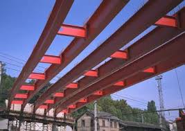
Can I assume (from the picture) that the unbraced length equals the distance between diaphragms?
 
Replies continue below

Recommended for you

Maybe... maybe not. It's a nuanced thing. Thankfully, there is Yura: Link.

c01_eipdqw.jpg
 
Likely you can assume the unbraced length for the individual girders is the distance between the diaphragms.

The unbraced length for each pair of girders is an entirely different matter. That is likely equal to the span length, if it's a simple span, or possibly more for multiple spans, depending on the bracing condition at the interior piers.

Rod Smith, P.E., The artist formerly known as HotRod10
 
Interesting. The weak axis (single girder) becomes strong axis (two girders assembly), so the consideration of unbraced length changes as well.
 
In other terms, if you're particularly interested in checking lateral torsional buckling of a single girder, yes, you can assume that the unbraced length is equal to the distance between the diaphragms.

If checking lateral torsional buckling of the global system (prior to deck curing), no, it is a different ballgame. I suggest you navigate the link KootK provided and follow the solution provided there.
 
retired13 said:
The weak axis (single girder) becomes strong axis (two girders assembly)...

Not exactly. It's actually only subject to LTB as a system if the girders are deep enough and close enough together that the vertical axis remains the strong axis of the system. Based on my perception of the proportions of the girder system in the picture, it's unlikely that the girder pairs would be susceptible to global LTB of the system, but looks can be deceiving, so I avoided dismissing the possibility.

Rod Smith, P.E., The artist formerly known as HotRod10
 
Rod,

Look again the Fig. 1 in KtooK's graph - individual vs global.
 
BridgeSmith said:
It's actually only subject to LTB as a system if the girders are deep enough and close enough together that the vertical axis remains the strong axis of the system.
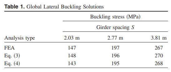
I don't believe that to be the case BridgeSmith. I agree that it would be if a longitudinal shear transfer mechanism existed to force the two girders to behave compositely. Here, however, such a mechanism does not exist. The clips shown below, from the Yura paper, show some examples of systems that are still prone to buckling with [composite Iy > 2 x Ix].

I envision the dual girder later torsional buckling problem as approximately [2 x single girder LTB + system warping resistance]. And in most practical cases, the latter term dominates.

c01_thz3ui.jpg

c02_ephjec.jpg
 
It’s a simple house project, where the single I-beam in the middle of a spacious living room, became too high(deep), L= 30 feet. The investors insisted on reducing the I-beam size.
So I decided to use two I-beams with diaphragms every 3-4 feet, (because there was a „pressure“ to use as little steel as possible), instead of two separate beams. The diaphragms will be 10 to 20 inches long. I am not sure why the longer of the two (if so) is better.

BridgeSmith said:
Likely you can assume the unbraced length for the individual girders is the distance between the diaphragms.

STrctPono said:
In other terms, if you're particularly interested in checking lateral torsional buckling of a single girder, yes, you can assume that the unbraced length is equal to the distance between the diaphragms.

Yes, LTB of a single beam, not LTB of the whole „ladder”.

Thanks for your help, I appreciate it.
 
10"? How tall are these beams? Just because the individual girders are LTB stabilized, that doesn't mean that LTB of the pair isn't still an issue. You can't just turn a blind eye to that piece of the puzzle.

Are you not able to brace the top flange of your beam to the floor or roof structure above? That's normally the case.
 
KootK and retired13, I was thinking about it incorrectly. More to the point, I didn't stop to think it through before I spouted off. Thanks for setting me straight. I remembered from an article on the subject there was a girder depth to girder spacing ratio where it wasn't required to check it, and I was thinking that was why, but you're right KootK, the two beams would need to act as a composite system to have that kind of resistance to LTB.

Rod Smith, P.E., The artist formerly known as HotRod10
 
Well that was easy. For an engineer, you've got an uncommon ability to roll with the punches and adapt to new information.
 
Your best beat to nut out the true buckling behaviour and hence the design capacity is to do a buckling analysis in these scenarios.

This will give you a reference buckling moment or sometimes a load factor by which the applied loads can be increased by. It's important to note this is not the design capacity.

You'll still need to apply normal code provisions to account for imperfections and residual stresses, etc. Just like you would if you were working out using your codes hand methods where instead of jumping to a buckling moment via an assumption around an effective length effective length, you are analysing a system to determine the actual buckling moment via the critical buckling mode (this implies an effective length if you wished to back calculate it out).

So instead of guessing a sometimes conservative effective length based on applying various factors to the member length based on the type of restraints, you're zeroing in on the theoretical effective length based on your boundary conditions/restraints that you modelled.

I recently did a series of blog posts on buckling analyses, the concepts are fairly universal even though I focused on the NZ & Australian steel codes, many other codes around the world deal with buckling analyses in a similar manner. Posts 1 & 2 are about the basics of an axial buckling analyses, posts 3, 4 & 5 are about flexural buckling analyses.

Regarding kootk's first post picture, you'll only get that higher mode of buckling between every diaphragm shown in (a) if the members are very stiff, forcing the higher mode of buckling is about stiffness. The other member is like a spring, make that spring stiff enough and you'll force a higher mode of buckling (this is quite easily demonstrated as per the blog posts I linked). Otherwise I'd imagine it will be more like both beams buckling together but in a constrained way provided the diaphragm adequately prevents the twist of the cross section. So as Klitor noted I'd expect the equivalent effective length is more likely to be over several diaphragm bays [EDIT... I'm talking here about the case before the bridge deck is in place to provide the final restraint].


I've been following this post with interest. Both because my previous interest in LTB behaviour and twin girder systems are something that we commonly use.

Agent666 said:
So instead of guessing a sometimes conservative effective length based on applying various factors to the member length based on the type of restraints, you're zeroing in on the theoretical effective length based on your boundary conditions/restraints that you modelled. I recently did a series of blog posts on buckling analyses, the concepts are fairly universal even though I focused on the NZ & Australian steel codes, many other codes around the world deal with buckling analyses in a similar manner. Posts 1 & 2 are about the basics of an axial buckling analyses, posts 3, 4 & 5 are about flexural buckling analyses.
Good post. And good blog posts. (I think I've already said that before, but no harm it extra compliments.)

I did have a quick play with this behaviour. With I-beams, reasonable diaphragm spacing, and without the top restrain from a deck you need to have pretty long spans to get the the global LTB effect. But it can be teased out as the primary buckling mode. Though through my brief analysis it does seem an edge case scenario for your typical I-beam pair. That said, not considering very much lead to trouble eventually.

The Marcy Pedestrian Bridge is an interesting read there are a few online papers on it.
 
KootK said:
Are you not able to brace the top flange of your beam to the floor or roof structure above? That's normally the case.

I’m not quite confident, that timber joists have enough bracing potential to restrain steel girders.

To simplify it a bit:
Girder Span= 9м
Load [LL+DL]= 20kN/m

1.First variant- Single girder- HEA360; weight=112kg/m.

2..Second variant- Twin girder with diaphragms (where the unbraced length is equal to the distance between the diaphragms 1.5м)- 2xHEA220; weight=2x50.5=101kg/m.

2..Third variant- Twin girder with diaphragms (where the unbraced length is equal to the distance between the diaphragms 1.5м)- 2xIPE300; weight=2x42.2=85kg/m.

For variants 2 and 3 LTB of the whole system is questionable.

Agent666 said:
Your best beat to nut out the true buckling behaviour and hence the design capacity is to do a buckling analysis in these scenarios.

I agree. But in this particular case I need some time saving rule of thumb.

human909 said:
I did have a quick play with this behaviour. With I-beams, reasonable diaphragm spacing, and without the top restrain from a deck you need to have pretty long spans to get the the global LTB effect.

Agent666 said:
So as Klitor noted I'd expect the equivalent effective length is more likely to be over several diaphragm bays.
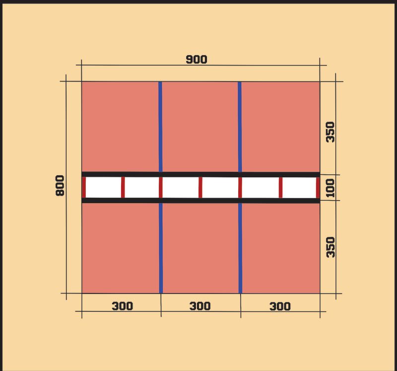
Am I on the safe side, if I skip buckling analysis and provide lateral restraints to the twin girder, doubling Lb. 2x1.5м=3м? (see the drawing)


twing_girder_k3ov7f.jpg
 
I’m not quite confident, that timber joists have enough bracing potential to restrain steel girders.

If they're connected, they should be adequate bracing. It takes very little restraint to keep the beams straight, unless they are allowed to move significantly.

I'm seen research for bridges with steel beams and timber decks indicating that friction between the timber and steel due to a truck load on the bridge is adequate to brace the beams against LTB. I'm not suggesting that would be the case in your situation, just illustrating that it doesn't take a particularly strong connection to restrain LTB (as long as the beams remain relatively straight).

Rod Smith, P.E., The artist formerly known as HotRod10
 
Am I on the safe side, if I skip buckling analysis and provide lateral restraints to the twin girder, doubling Lb. 2x1.5м=3м? (see the drawing)

Maybe safe, maybe not. You need to do an appropriate buckling analysis to answer that question. Guessing is often wrong, and the reality is you'll never know you're wrong. What if it's 3x1.5m=4.5m and your design is right on the money at 3m....

I don't buy into the excuse that it take too long or is too hard. Often you're building a model anyway to extract design actions, with the right software it take a few seconds to run the buckling analysis. The steel code I work with even takes less hand calculation steps to get to the design capacity from the results of a buckling analysis than working from estimating via a guess on the effective length.

If you want free options to investigate lateral torsional buckling, Google mastan2 or LTBeamN. Both will give you an idea of the buckling load even if you just model a single beam with appropriate restraints.
 
BridgeSmith said:
If they're connected, they should be adequate bracing. It takes very little restraint to keep the beams straight, unless they are allowed to move significantly
Agreed.

BLUEPUPIL said:
To simplify it a bit:
Girder Span= 9м
Load [LL+DL]= 20kN/m

1.First variant- Single girder- HEA360; weight=112kg/m.

2..Second variant- Twin girder with diaphragms (where the unbraced length is equal to the distance between the diaphragms 1.5м)- 2xHEA220; weight=2x50.5=101kg/m.
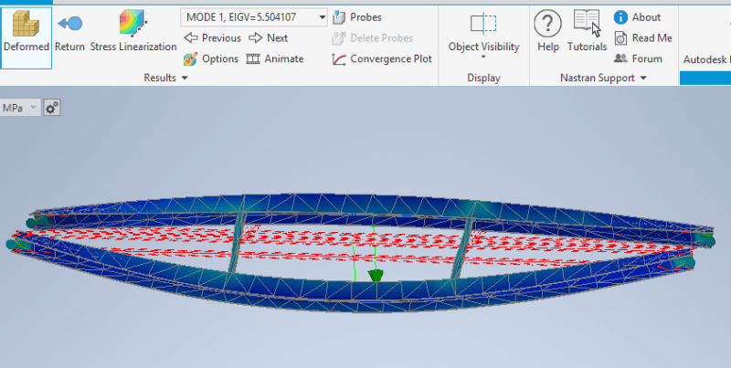
For 2xHEA220, LTB doesn't seem to be dominant even without considering the floor restraint which would be significant.

You get full length buckling at Mcrit of 5x for 2 diaphragms (3m spacing) and 10x for 5 diaphragms (3m spacing).

temp_sweaf6.png


Though as others have said you really should do this yourself. Don't rely on my rough and ready analysis.
 
What to use in order to get the job done fast and relatively easy?
1.Sap 2000
2.Risa 3D
3.Ram- Bentley
 
Status
Not open for further replies.

Part and Inventory Search

Sponsor