Continue to Site

Eng-Tips is the largest engineering community on the Internet

Intelligent Work Forums for Engineering Professionals

  • Congratulations waross on being selected by the Eng-Tips community for having the most helpful posts in the forums last week. Way to Go!

Two adjustments for one thread 4

Status
Not open for further replies.

LCform

Mechanical
Jan 13, 2016
139
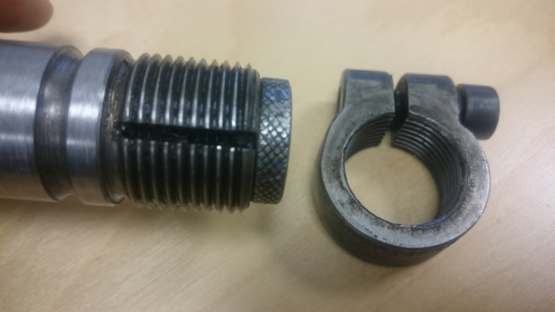
I have to reproduce a part, that at one end, it has externeal threads. While it is ribbed from sides, so a screw from inside, widens the diameter of this hole, but I see that also from outside, the ring that is going to be threaded on this shaft is also adjustable in tightness, my question is why there are two adjustable pieces used for this peice ? in the image you can see the piece
DSC_0015_jzr9cg.jpg
 
Replies continue below

Recommended for you

Well, the inside screw (thumbscrew on right of picture) increases the diameter of the screw. That increases friction, but doesn't absolutely stop movement of the clamp.

The outside clamp is tightened against that same inside threaded screw, but with an external clamp and machined threads, the clamp can be positioned firmly (no movement) at any point on the threaded shaft.

Minor advantage. When the diameter is made smaller on the external threads, the chance of galling or jamming the threads decreases slightly. But with lube? Not too much of a help.
 
It might help if we knew the function of the shaft.

It is a capital mistake to theorise before one has data. Insensibly one begins to twist facts to suit theories, instead of theories to suit facts. (Sherlock Holmes - A Scandal in Bohemia.)
 
The shaft rotates around an axis paralel to it's axis. or it's own axis, depending on the case of application, periodically for an angle of about 180 , at a frequency of 300 rev / min
 
To compensate from the eccentricity of tightening from one side only (pulling slightly off center when tightening)? The outer compensates for the inner. They have to be 180 degrees apart.(?)
 
I am interested in more info RE: the application as well.
 
the inner expander plug keeps the outer collar nut from changing position once set.
the outer clamping collar keeps the inner plug from coming out
[bigsmile]

could this be the evolution where one did not hold and thus the other was added latter?
 
If the thumbscrew - the piece that screws into the threaded end of the large shaft - is intended to be set at a particular length (axial distance from the shaft), then the thumbscrew can be turned to set a length desired. But turning the thumbscrew does not "lock" position.

Thus, the locking part. The external clamp locks the position of the thumbscrew.
 
The thumbscrew appears to be too small for the clamp to even touch it.

I think it looks like a field fix to make people wonder what he was doing. Or it was a "keep busy" project.
 
Thank you everybody, are there any specifications in standards, to tell us where we are obligated to apply the thumbscrew ?
 

JNieman said:
The thumbscrew appears to be too small for the clamp to even touch it.

Definitely. But the clamp is intended to clamp the threads (by compressing the slotted hollow outside length) of the thumbscrew , not the thumbscrew head itself.
 
LCform wrote "... are there any specifications in standards, to tell us where we are obligated to apply the thumbscrew ?"

racookpe1978 wrote "If the thumbscrew - the piece that screws into the threaded end of the large shaft - is intended to be set at a particular length (axial distance from the shaft), then the thumbscrew can be turned to set a length desired. But turning the thumbscrew does not "lock" position."

Can you provide a drawing showing how the device is used?

 
Again, without more info about the actual part, all I can offer is ASSumptive speculation.
The curious withholding of additional info can only invite false steps.

The knurl on the head of the screw suggests it will be turned by hand.
The external clamp //could// lock the the screw at any position.
MaYBe the function is to be a precisely adjustable positive stop ??

I just realized this is similar to what racookpe1978 proposed.
 
Wait a minute, I thought the internal thumb screw opened the hole in the shaft like an adjustable reamer? Communication needed here!
 
an easiy test to see if the thumb screw is an "expander" or an "adjustment" would be observe as the thumb screw is inserted.
If it gets harder to turn AND causes the shaft threads to enlarge significantly, it is an expander.
if it just screws in and out, it is some sort of adjustment for an yet to be determined device requirements.

with out the thumb screw, what purpose would the collar serve? to retain a bearing?, limit a stroke?
what is the groove for? an oring?
 
The thumb screw in the photo is turned all the way in but the slot is still parallel. Suggests it is not an "expander" doesn't it?

je suis charlie
 
If the internal screw thread is straight then maybe the inner screw is meant to be an adjustable axial stop.
 
If this is a single replacement part, and the function is not obvious I would wager with byrdj on evolution.
The inner screw was most likely the original design and when it didn't hold well enough they added the external clamp.

 
What an interesting puzzle. I'm almost cheering for the OP to keep us guessing, just for the fun of it.
Of course, if the OP seriously expects anyone to guess right, he would have to provide more information: where does the shaft come from; what is clamped to the shaft, etc....

I've written two guesses in the past 5 minutes and deleted both... but no that's not it...

Current guess is that the internal thumbscrew has nothing to do with expanding the tip of the shaft. The fact that it can is just a side-effect. This conjecture is based on my own assumption that the shaft is hollow and that a fluid must flow through the center of the shaft. The combination of thumbscrew and female clamp sets the size of the opening in the slot in the end of the shaft, metering the flow. I drew some strange oilfield stuff... a long time ago.

STF
 
Hello Again All

and thank you for showing interest in this question. Well to be honest the reason I did not mention the application was that I don't have access to the other parts. but it's part of the transfer mechanism in a cold forming of bolts - machine, that as I have mentioned how it functions before, so there is another clamp that is screwed under the above clamp, which has an arm that is connected to a mechanism to grab the peices to move them between the dies of different steps.

the pieces are very small and not a big force is required to hold them so as in one of the post it's mentioned by a sketch , which is represented correctly, you might first close the clamps , the insert the thumbscrew. the slot is only to let the threads of the shaft to expand obviously. so the only factor that has made this machanism be applied , is that probably the high speed of the movement, causes the screw to loosen. and maybe the guy who designed this, had an experience in automotive or jig and fixture design. but I don't find an standard to say how it is designed
 
Status
Not open for further replies.

Part and Inventory Search

Sponsor