Eng-Tips is the largest engineering community on the Internet

Intelligent Work Forums for Engineering Professionals

Two machines on same structure - combined vibration question 2

Status
Not open for further replies.

ldeem

Structural
Sep 2, 2013
256
0
16
US
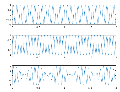
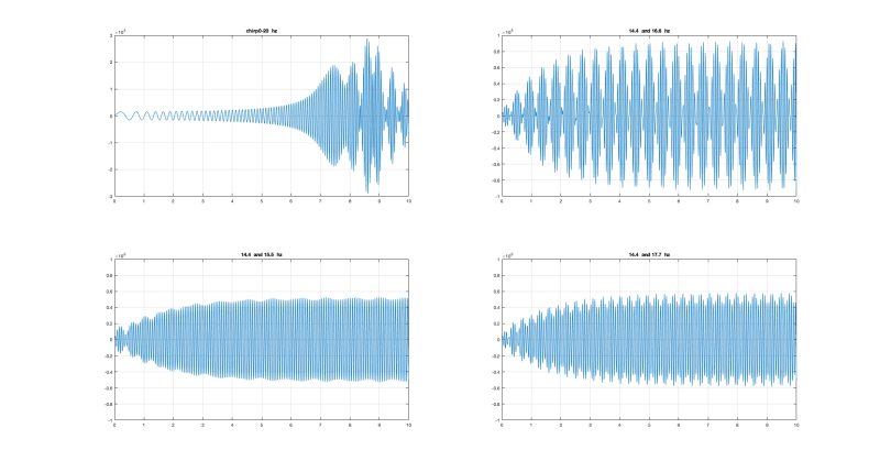
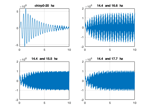
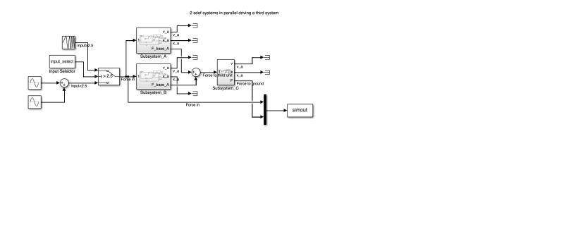
I have a structure with two vibrating screens (14.4 Hz and 16.6 Hz) they are on separate levels but share columns. We are having a lot of trouble with one screen but no one has been able to find vibration reading that show a problem. My question is how do the vibration forces combine from two different pieces of vibrating equipment? I have read about beat frequencies but that seemed very specific to audio frequencies. Plus (as I understand beat frequencies) it would be 16.6-14.4=2.2 Hz. When I do FFT from my field reading I don't see anything in this area. I am recording 59 seconds of data so it seems like I should collect several instances of a 2.2 Hz signal.

Is it possible the two signals could peak at the same time but infrequently? I am wondering if that is happening and sending a shock wave through the structure but it just hasn't been captured in recording data yet.

FFT's shows strongest reading at the machine vibrating frequency. So that gives me confidence my data collection and analysis is ok.

The machine supplier has said the structure is at fault but they haven't shared their data or said that some parameter is out of spec.
 
Replies continue below

Recommended for you

What problem is being seen? Whether you see the difference frequency is going to depend on transmissibility and damping through the rest of the structure. I assume since the building isn't crumbling that it does not share any of them as a natural frequency.
 
Plus (as I understand beat frequencies) it would be 16.6-14.4=2.2 Hz. When I do FFT from my field reading I don't see anything in this area.
The addition of a sinusoid at 16.6 and a sinusoid at 14.4 will indeed cause a beat at 2.2hz. But you won't be able to see it in the spectrum (other than noting there are peaks at 16.6 and at 14.4). Assuming there's not a lot of other frequencies present, you will be able to see it in the TWF (if it is long enough let's say in this case 5 seconds).

It reflects simple trig identities, like
[cos(A-B) + cos(A+B)] = 2*[Cos(A)*cos(B)]

A beat is not necessarily a problem. It is often just more noticeable with our senses. I agree with previous poster, we don't really know what the problem statement is.

=====================================
(2B)+(2B)' ?
 
ldeem,

If you have two vibration sources, the amplitudes add together, giving you maximum displacement, velocity and acceleration. Your structure needs to cope with this. Your structure must not resonate at either frequency.

Let's be practical. Is there any need for your structure to be light weight? Can you reinforce it and make it stiffer?

--
JHG
 
As electricpete says, FFT does not really show beats, time domain analysis is the best way of showing them. As they are independent sources, at different frequencies, they should add, as his equation shows. So when they add at peaks, all other things being equal, you are seeing double the amplitude, and hence double the strain, and hence 32 times more fatigue damage.

A sketch of the layout would be handy.

The solution is the same as any other cyclic vibration problem, reduce excitation, isolate, or change the structure.

Cheers

Greg Locock


New here? Try reading these, they might help FAQ731-376
 
If the FFT settings are right so that you can watch the vibration FFT for a while "real time" you might see the 14.4 Hz and 16.6 Hz dancing and swapping amplitudes rising and falling a few times ~ every second.

Like what happens on my old Volvo around 60 mph when the steering wheel vibration increases and then fades to nearly zero every 10-20 seconds. I imagine the tires are rotating at slightly different RPM, and the wheel/tire unbalances add for a little while, and then cancel out, taking advantage of some small looseness in the steering or Macpherson strut suspension.
 
Doesn't work like that in the simplest case. The amplitude of the fft at the two frequencies doens't change with time

beat_kthrvq.png


Cheers

Greg Locock


New here? Try reading these, they might help FAQ731-376
 
Thank you everyone for the thoughtful information.

The structure is existing and is basically a two level braced steel frame with a vibrating screen (spring isolated machine) on each level. The original design worked well and ran for several years. The top level screen was changed out for one that runs at the same frequency but has a much greater dynamic load. This resulted in high measured velocities which were fixed by adding additional supports.

The top level screen continues to experience frequent spring isolator breakage. The equipment supplier has stated the structure is the problem but they do not provide any data to support their claim.

Another engineer recently focused on the two screen somehow affecting each other in a negative way. This got me to thinking about how the two screens may vibrate in sync at some frequency that is near a natural frequency of the structure. I can understand how the amplitude of the two sources of vibration would combine by principals of superposition but I couldn't figure out what the resulting frequency would be since the two sources can start at different times. That is when I read about beat frequencies but all the literature I found was related to audio signals.

I think my question has been answered (thank you to everyone); that is yeas the two sources of vibration will combine and it will be the difference in frequencies. Now I need to go back and look at my strural anays to see if I have any modes near this frequency.

Does anyone have a good reference book suggestion for this type of problem?
 
I suspect you would already know if there were any natural frequencies near these by the pounding on your feet while in the building.

It sounds more like the isolators are not suited for the new, larger loads. You could test this by running just the lower machine and see if any vibration is moving the mounts for the upper screen by more than a few percent of the travel when the upper machine is running. I suppose it's possible the upper isolaor springs have a natural frequency matched to the primary mode of the lower machine, but you will see that running the lower one alone as well.
 
In order for spring isolators to correctly attenuate vibrations, their natural frequencies need to be around 0.1x of the disturbance. If your machinery vibrations are in the teens of Hz, then your isolations need to be in the low single digits Hz. That's not unheard of; we used build something that was mounted above the rotor of a helicopter and our isolators were down around 1 Hz, for an 8-Hz blade frequency.

TTFN (ta ta for now)
I can do absolutely anything. I'm an expert! faq731-376 forum1529 Entire Forum list
 
I think my question has been answered (thank you to everyone); that is yeas the two sources of vibration will combine and it will be the difference in frequencies. Now I need to go back and look at my strural anays to see if I have any modes near this frequency.

Just to circle back, if you have machines at 16.6 and a sinusoid at 14.4, that will indeed cause a beat that sounds like 2.2hz. But it should not excite any resonance at 2.2hz. In amplitude modulation terminology, the 2.2hz (or actually half of it... 1.1hz) plays the role of an “envelope” frequency and (14.4+16.6)/2 = 15.5hz plays the role of the “carrier frequency.

More specifically, let’s look again at that simple trig identity I mentioned: [cos(A-B) + cos(A+B)] = 2*[Cos(A)*cos(B)]
Let A = 2*pi*15.5*t; and B = 2*PI*1.1*t
Then the left side of the identity is cos(2pi*15.5*t -2pi*1.1*t) + cos(2pi*15.5*t +2pi*1.1*t) = cos(2pi*16.6*t) + cos(2pi*14.4*t)
And the right side is 2*[ cos(2pi*15.5*t)*cos(2pi*1.1*t)
LHS = RHS...
cos(2pi*16.6*t) + cos(2pi*14.4*t) = 2*[ cos(2pi*15.5*t) * cos(2pi*1.1*t)
These are just different ways to express the same thing. The left side is a sum of sinusoids, the right side is a product of sinusoids.
The right side is what you’d recognize easily in the time waveform.
The left hand side is what you’d see in the spectrum. 2.2hz does not appear in the spectrum and will not excite any resonance. Adding excitations at different frequencies does not create any new frequencies in a linear system.

Sorry if I misunderstood your comment.


=====================================
(2B)+(2B)' ?
 
electricpete - thank you for the detailed explanation. I can understand the carrier frequency idea from my days as a electrical technician but I have a hard time understanding why the carrier wave could not create an excitation that matches the carrier wave frequency.

Consider I have two pieces of equipment on spring isolation bases. They both move in oval pattern but for the sake of this discussion consider just the forward and back motion. They both operate a different speeds but occasionally both will be at the far forward position at the same time. So at that time both are creating a force through their isolation systems in the same direction at the same time. The frequency of this occurrence (I think) is then the 2.2 Hz and the amplitude the sum of the two forces. Is this not the right way to think about it?

On to a second question, I looked at some similar screens and isolation spring resonance is commonly around 2.2 Hz. If what I wrote in the above paragraph is happening would it make sense that the spring is being excited near its resonance frequency and so seeing very large forces in the spring?
 
> electricpete - thank you for the detailed explanation. I can understand the carrier frequency idea from my days as a electrical technician but I have a hard time understanding why the carrier wave could not create an excitation that matches the carrier wave frequency.

Perhaps my idea to mention amplitude modulation made things way more complicated than they need to be. A signal with modulation index <1 will have carrier frequency present but a signal with modulation index 1 will not.

Forget amplitude modulation and look at the trig identity. It is an equality. Only one side of the equality represents the spectrum (the side that is the sum of sinusoids). That side of the equation has only the machine frequencies, not the difference frequencies. The other side is the side where half the difference frequency shows up as an multiplier (envelope).

You mentioned superposition. Superposition relies on having a system that is linear time invariant. In a steady state LTI system, the only frequencies that are present are the frequencies of the excitation (input). That's because the only operations done within such system are addition, multiplication by a scalar, differentiation, integration, delay...none of which can transform a sinusoid to a sinusoid of a different frequency. It's an important concept imo.

> Consider I have two pieces of equipment on spring isolation bases. They both move in oval pattern but for the sake of this discussion consider just the forward and back motion. They both operate a different speeds but occasionally both will be at the far forward position at the same time. So at that time both are creating a force through their isolation systems in the same direction at the same time. The frequency of this occurrence (I think) is then the 2.2 Hz and the amplitude the sum of the two forces. Is this not the right way to think about it?

I'd say it's correct that you have a peak of the envelope occurring at a repetition rate of 2.2hz, but you don't have a signal that is exactly periodic at 2.2hz (or 1.1hz) if you look closely at what the signal is doing within that envelope. If you created such system and looked at it on a spectrum analyser (frequency domain) you should see only 16.6hz and 14.4hz. If you looked at it on an oscilloscope display (time domain) you could make out features related to 2.2hz/2 and 15.5hz, both those frequencies are not present in the spectrum and will not excite a resonance.

=====================================
(2B)+(2B)' ?
 
Question for the panel

consider a single degree of freedom spring/mass/damper system
Tune it to 2.2 Hz

Apply the 14.4 and 16.6 Hz, forces, simultaneously.

What frequency(s) will it vibrate at?

Now run it at 14.4 and 15.5, or 14.4 and 17.7

Is the amplitude greater or smaller?

My guess is that the 15.5 case will give the biggest maximum displacement, simply because we have a lower frequency input into a low pass filter. The 2.2 is not a real physical excitation in some fundamental fashion.


Cheers

Greg Locock


New here? Try reading these, they might help FAQ731-376
 
Thank you again for everyone's time on this. I clearly need to study this concept some more since the match and what I am intuitively thinking about motion of the machines is not correct.
 
and then this is the two tables sat on a third mass, which has a resonant frequency by itslef of 2.2 Hz

This is the force into the ground

three_dof_jewrme.png


here's the model

threedofmodel_kqsoyt.png


So the 2.2 hz exists, it is excited by the chirp, but makes no odds to the response to the excitation at 14.4 + 15.5,16.6 and 17.7 Hz.

Note that this model assumes that the subframe is very heavy compared with the vibrating tables, which may or may not be true. I'll come up with a better model later.

Cheers

Greg Locock


New here? Try reading these, they might help FAQ731-376
 
Status
Not open for further replies.
Back
Top