Eng-Tips is the largest engineering community on the Internet

Intelligent Work Forums for Engineering Professionals

Two machines on same structure - combined vibration question 2

Status
Not open for further replies.

ldeem

Structural
Sep 2, 2013
256
0
16
US
I have a structure with two vibrating screens (14.4 Hz and 16.6 Hz) they are on separate levels but share columns. We are having a lot of trouble with one screen but no one has been able to find vibration reading that show a problem. My question is how do the vibration forces combine from two different pieces of vibrating equipment? I have read about beat frequencies but that seemed very specific to audio frequencies. Plus (as I understand beat frequencies) it would be 16.6-14.4=2.2 Hz. When I do FFT from my field reading I don't see anything in this area. I am recording 59 seconds of data so it seems like I should collect several instances of a 2.2 Hz signal.

Is it possible the two signals could peak at the same time but infrequently? I am wondering if that is happening and sending a shock wave through the structure but it just hasn't been captured in recording data yet.

FFT's shows strongest reading at the machine vibrating frequency. So that gives me confidence my data collection and analysis is ok.

The machine supplier has said the structure is at fault but they haven't shared their data or said that some parameter is out of spec.
 
Replies continue below

Recommended for you

I made what I think s a correct model for the situation I am asking about. Also attached as PDF

Screenshot_2021-11-08_083027_xldkpg.jpg
 
Those were some interesting results Greg. The envelope of the excitation (AM pattern) seemed to carry through to the envelope of the particular response that you graphed better in the case when the envelope frequency matched that natural frequency. I'd like to try to understand that better at some point although I'm holding any questions to avoid hijacking op's thread.

I could guess some interesting relative model values and I'll bet Greg could guess even better. I wonder if op can share with us more details of what he has measured in terms of spectra or TWF on the machines (and maybe the structure? and maybe bump tests?). ok, maybe that's too much to ask for... the first question just to double check: were both frequencies 14.4 Hz and 16.6 Hz evident on the spectrum of the troublesome machine? (and what were their relative magnitudes, and was directionality apparent in one or both frequencies)

=====================================
(2B)+(2B)' ?
 
electricpete said:
I'm holding any questions to avoid hijacking op's thread.
.
Ahhh... the heck with it!

Greg said:
Question for the panel

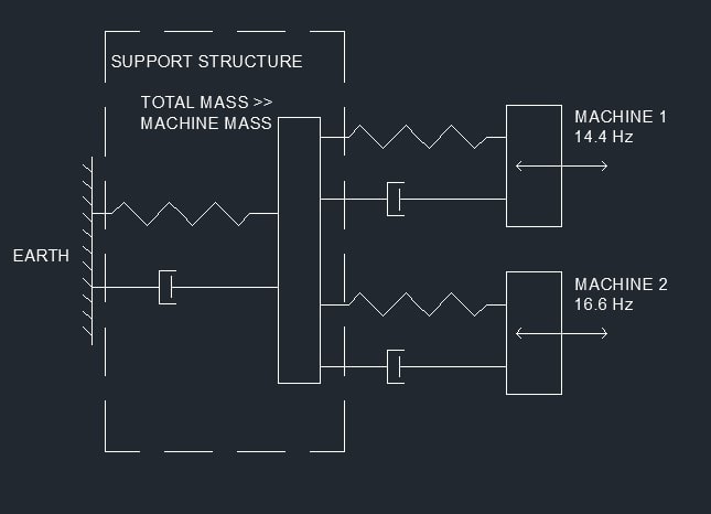
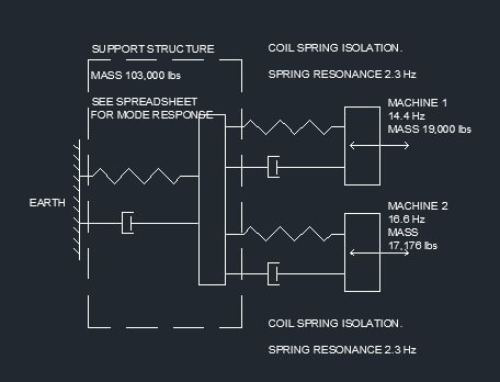
consider a single degree of freedom spring/mass/damper system
Tune it to 2.2 Hz

Apply the 14.4 and 16.6 Hz, forces, simultaneously.

What frequency(s) will it vibrate at?

Now run it at 14.4 and 15.5, or 14.4 and 17.7

Is the amplitude greater or smaller?

My guess is that the 15.5 case will give the biggest maximum displacement, simply because we have a lower frequency input into a low pass filter. The 2.2 is not a real physical excitation in some fundamental fashion.

I'd like to revisit that question and try to understand your results.

My logic agrees with what you said in that post above. We have a linear system model. We can predict the responses to each of the sinusoidal inputs. The total response waveform is the sum of the individual response waveforms.

Now one question is how do we characterize that sum waveform in terms of a magnitude. There are two common options:
[ul]
[li]1 - RMS. The RMS of the total response should be the sqrt of the sum of the squares of the RMS of the individual responses. But we can't judge that from the waveform, so it's not worth further discussion. [/li]
[li]2 - True peak. ASSUMING (assumption 1) that the frequencies are not related by a ratio of integers, then we know that the "phase" relationship between the two peaks (maybe strictly speaking I can't call it phase, we can also call it the time between the positive peak of the two sinusoids) will drift somewhat randomly between 0 and half the period of the higher frequency sinusoid. Therefore ASSUMING (assumption 2) we examine the waveform over a sufficiently long period of time, then they will eventually line up so that their peaks are at/near the worst case combination (which gives the peak of the sum as the sum of the peaks) at some point during that long simulation.[/li]
[/ul]

That's how I think it should work. So ASSUMING (assumption 3) that indeed the 15.5 has a lower individual response than the 16.6 and 17.7, then I'd expect the peak of the combined waveform would be highest when we combine 14.4 with 15.5 (rather than combining it with 16.6 or 17.7)

But that is not what we see on your graphs. The system including 16.6 input gives the highest combined peak. So in my mind, among the three assumptions identified / bolded above, one of them must be wrong:
[ul]
[li]Assumption 1? Sure we violated the "ratio of integers" assumption (since our frequencies are not irrational numbers), but those integer ratios are high enough that I doubt that is the problem[/li]
[li]Assumption 2? The simulation looks like it has run long enough so that the peaks have stabilized and we are close to the true peak so I doubt that is the problem.[/li]
[li]Assumption 3? This has my vote for the assumption that was violated. Mabye the individual response of 15.5 is not lower than the individual response to 16.6 and 17.7 for the particular system and output that your are plotting. I have to immediately followup by admitting that I don't understand exactly what your system looks like and what is the output that you are plotting.[/li]

[/ul]
That's the way I see it, maybe I'm completely missing something somewhere.

Another unmistakeable feature of the graphs as mentioned before is the envelope of the input shows up in the response much better in the combination with 16.6 (where the envelope frequency matches a resonant frequency). I have no idea why that would be.


=====================================
(2B)+(2B)' ?
 
(a) I don't know of a mathematical reliable way to do envelope analysis. If you do RMS then the heterodyning vanishes.
(b) I've decided I don't really like that model
(c) it is two mass/spring SDOF blocks in parallel, sitting on top of a grounded sdof block. So it is the same architecture as Ideem drew. Due to a modelling assumption that is incorrect the results can only be correct if the mass of the thrid sdof block >> mass of the other two.

Cheers

Greg Locock


New here? Try reading these, they might help FAQ731-376
 
Sorry, I have been out of town a few days and just now getting back to my computer.

GregLocock, can you tell me what k,m c are? I can guess k is spring constant and m is mass but not sure what c is.

I have recorded acceleration data after machine 1 (where machine 1 attaches to the main structure), I would be happy to share the raw data if it is of use. I have used it to calculate velocities using Vibration Data Toolbox.

Prior to modifications I did a startup and shutdown to verify my model frequencies. They were in the ball park. The structure has since been modified and I haven't done any new shutdown tests.

Main issue is machine 1 springs keep failing. The equipment supplier doesn't provide any guidance on maximum support structure velocities (or any other dynamic acceptance criteria).
 
GregLocock

Here are the weights and some of the dynamic information added to the schematic.

A printout of all the structural frequencies is in the attached excel file.

Either this post or the next (if the file doesn't attach) are the velocities I measured on the machine 1 base at three different dates. The 10/20/2020 is before structural modifications.

Screenshot_2021-11-13_092537_i7vnur.jpg
 
There are two machines on a two level braced frame structure. Machine 1 is on the top level and machine 2 is on the second level.

The vibrating screens are for aggregate processing.

It looks a lot like the link below except there is another screen below the top screen.

The screen/machine is for sorting rocks into different sizes. It's basically multiple levels of big mesh screens that sit inside a frame that is supported on springs. A motor with eccentric weights spins around and causes the frame to vibrate at the frequencies in the diagram. The problem is springs on machine 1 keep breaking. I thought maybe the two machines running at the same time were creating a "new" vibration in the structure by superposition and that was close to a resonance in the structure which in turn was causing the springs to break.

Based on what I read in the thread superposition is not the right way to think about the problem.

Link
 
Beating, heterodyning, whatever, is always a confusing topic.

Given that the only coupling between the two lightweight screens is a five ton frame, conceptually it seems unlikely that screen1 is going to have much effect on screen2.

I'll have to rejig my model a bit, then I'll pull out the spring forces.


Cheers

Greg Locock


New here? Try reading these, they might help FAQ731-376
 
It seems like observation of the system would be most helpful. Fire up one of the shakers and see what it does and then fire up the second one and see if the first one responds any differently. Then shut off the first one and see if the second one responds any differently.
 
> Based on what I read in the thread superposition is not the right way to think about the problem.

I don't think anyone objected to superposition (the response at any location is likely the sum of the individual responses you'd get from each machine running). It's just the idea that superposition creates a new frequency that was objected to.

=====================================
(2B)+(2B)' ?
 
Status
Not open for further replies.
Back
Top