Continue to Site

Eng-Tips is the largest engineering community on the Internet

Intelligent Work Forums for Engineering Professionals

  • Congratulations SSS148 on being selected by the Eng-Tips community for having the most helpful posts in the forums last week. Way to Go!

Two Port Networks

Status
Not open for further replies.

DistCoop

Electrical
Jan 2, 2013
83
Does anyone know if this circuit has a name, or better still have an idea of how to solve? If I have a known current and voltage I1 and V1, how is the current through each impedance element determined? I've searched through filter design literature without success, and have attempted deriving ABCD parameters... surely this has been seen and solved before.
Thanks
2_Port_fmgwbx.png
 
Replies continue below

Recommended for you

Your diagram also shows an I2 and a V2. I don't think you mentioned those.

Did you intend one or either of them to be fixed? If so, that may reduce the number of unknowns to the point where the problem becomes a lot easier.

Whatever is connected between the two terminals at the right hand edge of the diagram is going to form part of the network you want to analyse - defining that properly might help too.

A.
 
Assume that I know V1 and I1, but do not know V2 or I2.

You mentioned whatever is connected externally will affect the circuit... that's why I was hoping to use ABCD parameters to define this circuit topology. Then I can simply multiply the ABCD matrix by that of whatever I'm connected to (I hope)
 
It's composed of resistive and inductive elements in reality, at 60Hz.

I attempted the ABCD derivation but something isn't coming out right. I'm curious if this is a commonly seen circuit by some. In my search I can't find a similar example
 
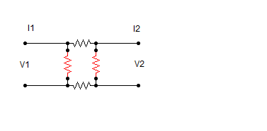
To find the value of A, evaluate V1/V2 with the right-hand side of the circuit open (therefore I2 = 0).
To find the value of B, evaluate V1/I2 with the right-hand side of the circuit shorted (therefore V2 = 0).
To find the value of C, evaluate I1/V2 with the right-hand side of the circuit open (therefore I2 = 0).
To find the value of D, evaluate I1/I2 with the right-hand side of the circuit shorted (therefore V2 = 0).

If it helps, you can break the circuit into three smaller two-port networks: the left shunt admittance, the two middle series impedances, and the right shunt admittance. Find the ABCD matrix representation of each, and then simply multiply the three ABCD matrices in order from left to right (remember, matrix multiplication order matters). That's how I solved your problem. If you post what you think the correct answer is, maybe someone will tell you if you've gotten it right.[smile]

By the way, I assumed both I1 and I2 go from left to right when I worked the problem, so I don't have the same sign convention in Figure 1 in the Wikipedia link. No big deal; it just means I don't need the negative signs when determining C and D.


xnuke
"Live and act within the limit of your knowledge and keep expanding it to the limit of your life." Ayn Rand, Atlas Shrugged.
Please see FAQ731-376 for tips on how to make the best use of Eng-Tips.
 
Such circuits can always be solved, often using the concepts of Kirchhoff. Kirchhoff's Laws give you the extra equations needed to solve for all of the unknowns.

Google: Kirchhoff's laws

 
The two-port network for the shunt branch of Z1 as you defined in the image is:
Min has A = 1, B = 0, C = 1/Z1, D = 1
The two-port network for the middle series components of Z2 and Z4 as you defined in the image is:
Mmid has A = 1, B = Z2+Z4, C = 0, D = 1
The two-port network for the shunt branch of Z3 as you defined in the image is:
Mout has A = 1, B = 0, C = 1/Z3, D = 1

Matrix multiplication of the three matrices should give you the correct answer for the overall network: M = Min*Mmid *Mout.

xnuke
"Live and act within the limit of your knowledge and keep expanding it to the limit of your life." Ayn Rand, Atlas Shrugged.
Please see FAQ731-376 for tips on how to make the best use of Eng-Tips.
 
Can you multiply them in series? The middle two aren't really in series with each other and with the other 2 branches
 
I responded to quickly. You say there are 3 matrices. How can Z2 and Z4 have their own? With Z1 and Z3 in between, how can Z2 and Z4 have their own matrix?
 
If you can create cuts so that there are two terminals on each side, you've created two port networks. Cut to the immediate right of Z1 and the immediate left of Z3, and you have a middle two-port network with Z2 in the top branch and Z4 in the bottom branch.

xnuke
"Live and act within the limit of your knowledge and keep expanding it to the limit of your life." Ayn Rand, Atlas Shrugged.
Please see FAQ731-376 for tips on how to make the best use of Eng-Tips.
 
That's a much better method... thanks for the idea.

A = 1 + (Z2 + Z4) / Z3
B = Z2 + Z4
C = 1/Z1 + (1/Z3)*(1+(Z2+Z4)/Z1)
D = 1 + (Z2+Z4)/Z1

A*D - B*C = 1
 
That looks correct! [bigsmile]

xnuke
"Live and act within the limit of your knowledge and keep expanding it to the limit of your life." Ayn Rand, Atlas Shrugged.
Please see FAQ731-376 for tips on how to make the best use of Eng-Tips.
 
Have you considered scattering (S-) parameters? They are typically used for this type of models at much higher (RF) frequencies.

Z
 
Status
Not open for further replies.

Part and Inventory Search

Sponsor