Continue to Site

Eng-Tips is the largest engineering community on the Internet

Intelligent Work Forums for Engineering Professionals

  • Congratulations KootK on being selected by the Eng-Tips community for having the most helpful posts in the forums last week. Way to Go!

Two pumps in series in constant pressure mode 2

Status
Not open for further replies.

VapourSnow

Specifier/Regulator
Mar 22, 2019
9
Could two centrifugal pumps of the same type be used in series in constant pressure mode, where the pumps are set to deliver different heads please?
The system is a closed circuit, which can operate in two different modes:

Mode A: Only pump 1 operates, zone valve closed for circuit with pump 2. Load can vary, pump 1 maintains constant pressure, with minimum flow ensured by a differential pressure bypass valve.

Mode B: Both pumps operate, fixed load, higher pressure and flow required than in mode A. Pumps would be well apart in the system, with part of the load between discharge of pump 1 and suction of pump 2; and the rest of the load between discharge of pump 2 and suction of pump 1.

I could find very little information about running pumps in series in constant pressure mode; so any help or guidance would be very much appreciated thanks.
 
Replies continue below

Recommended for you

In short yes.

Mode B sounds very much like a booster pump mode which is quite common. A lot will depend on the speed of response of each element to avoid instability of flow or one attempt fighting against the other.

A decent diagram of control loops would help. Why the impotence of constant pressure?

Remember - More details = better answers
Also: If you get a response it's polite to respond to it.
 
Thank you LittleInch for the reply, that's encouraging.

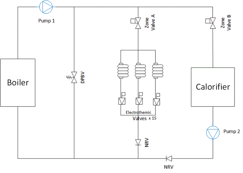
Diagram of system:
0408_Heating_and_Piping_Process_Flow_0-16_u3iluy.gif


Zone Valves A and B are exclusive, if one's open the other will be closed. Zone Valve response time open-closed 75 secs
Pump B would be switched through Zone Valve B, so would not operate until Zone Valve B is 85° open (90° is fully open).
Electrothermic valves can be anywhere between all open and 1 open; there are 15 loops. Electrothermic valve response time open-closed 5-6 mins

Constant pressure is important for mode A, so that flow decreases as electrothermic valves close, so that the temperature differential is maintained as wide as possible for condensing boiler efficiency. (Proportional pressure would be even better, but is not compatible with the DPBV to maintain minimum flow rate through boiler.)

Pump 2 doesn't have to be in constant pressure mode, as the hydraulic resistance is fixed in mode B.

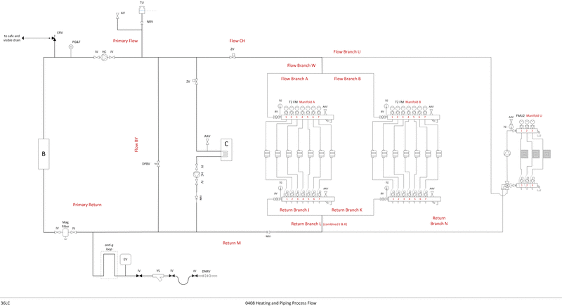
Please also find a schematic of the full system as well, in case that detail is useful:
0408_Heating_and_Piping_Process_Flow_0-17_full_rjrhhg.gif


Link to image as that looks too small to read:
I hope I've provided sufficient information, please let me know if I've missed something. Thanks for your help, I really appreciate it.
 
There is a check valve shown on the combined exit from the 2 banks of electrothermic valve heating banks on your first sketch, but not on the detailed P&I D. So what is the problem here? There may be a short duration when pump 2 doesnt develop pressure, but that would depend on the sequencing between zone A and zone B shutdown valves at the time when moving from mode A to mode B, which you havent said much about yet. If zone A valve closes fully first, followed by zone B valve opening, then there would be no transient low pressure on pump 2 discharge pressure as it starts.
 
Thanks George for the guidance. The check valve is after the combined exit from the 2 banks of electrothermic valve heating banks, apologies for the mistake, I have corrected the detailed P&ID.

Sequence when transitioning from mode A to mode B:

00 secs: [tab]zone valve A open (90°), [tab]zone valve B closed (00°), [tab]pump 1 on, [tab]pump 2 off
01 secs: [tab]zone valve A starts to close (01°), [tab]zone valve B starts to open (89°), [tab]pump 1 on, [tab]pump 2 off
38 secs: [tab]zone valve A half closed (45°), [tab]zone valve B half open (45°), [tab]pump 1 on, [tab]pump 2 off
71 secs: [tab]zone valve A nearly fully closed (05°), [tab]zone valve B nearly fully open (85°), [tab]pump 1 on, [tab]pump 2 switches on
75 secs: [tab]zone valve A fully closed (00°), [tab]zone valve B fully open (90°), [tab]pump 1 on, [tab]pump 2 on


With pump 2 starting when the zone A valve nearly closed, and with the additional check valve on the mode 1 heating banks included, there shouldnt be any undesirable transients. Since mode B runs open circuit without any control valves inline, pump 2 discharge pressure should be more or less constant, so there is no need for a diff pressure control valve in this mode B.

What appears to be the expansion drum (marked TU) for this circuit is shown downstream of pump 1. Typically the drum would be upstream of the circulation pump. Is this drum N2 blanketed under constant pressure ? Does this drum maintain constant level and pressure in both modes A and B?
 
Thanks George for the advice and guidance.

The expansion vessel is at the bottom of the diagram mark EV. (TU is a top-up unit, mainly for commissioning and maintenance.) The expansion vessel is pre-charged with Nitrogen.
I think I see the issue, in mode B this EV would come under pressure from pump 2 at its current proposed connection point to the system.
Whilst I believe best practise is to connect the EV on the return; if I connected it on the flow side of the boiler prior to pump 1 suction, I think it would then maintain pressure in both modes A and B without being under pressure from either pump in either mode. Please see attached revised P&ID v0.18
 
A closer look at this circuit tells me the location of this expansion drum could be either upstream or downstream of the boiler provided flow in modes A and B is the same. If flow in both modes is not, then I cannot see this expansion drum working in either location, since the blanketing pressure at the EV is presumably fixed.

When flow is the same in both modes, pressures upstream and downstream of the boiler are invariant.

Cannot see what this anti g loop is for downstream of the EV, since this EV is pressurised. You do need low level, high level and high /low pressure safeguards at the drum.
 
Thanks George. The flow is greater in mode B than mode A; also the flow varies within mode A as the electrothermic valves open and close. Expansion Vessel blanketing pressure is fixed.
If the Expansion Vessel is connected between the boiler and pump 1, I think that would work as the variations in pressure at this point, for either flow, would be minimal. With all parts of the system being under positive pressure. Am I missing something please?

The anti-g loop is a CIBSE recommendation to have a section of pipe that goes up, across and down, to prevent heated water from the system rising into the Expansion Vessel.
 
Sorry, the EV would work okay ( level would remain constant ) even when flows change between modes A and B. Basically, the EV sets the pressure at its tee in to the recirculation loop.

I still cannot see what this anti g loop is doing here.

Usually the EV is placed upstream on pump 1, and is inline with this main flow ( main flow goes into EV, exit from EV goes into pump suction), rather than sitting on a tee off. This helps with system priming on startup (to clear air bubbles on startup). What are you heating here in manifolds A and B and U? Is there a possibility of reverse flow of process fluids at these heaters into this hot water circuit in the event of a heat exchanger leak ? This is the other reason for having this EV inline and upstream of the pump 1 - to allow release of any volatiles at the EV due to reverse flow of high pressure fluids at these heat exchangers. Check that you've got an overpressure / backpressure regulator at the EV, in addition to the forward sensing (low set) breathing N2 regulator.

Another important requirement for system priming on startup is to locate the EV at the highest point of this whole circuit- again this is to facilitate priming of the recirc loop.

 
Thanks George. Manifolds A and B are for radiators and U for underfloor heating. So any leaks would be to atmosphere.

The EV has a butyl rubber diaphragm whose lifespan can be reduced by exposure to higher temperatures. The EV is at a high point (TU is higher; with a NRV), so the anti-g loop is to stop hot water rising into the EV, shortening its life.

There are Automatic Air Admittance Valves to release air.
There is an overpressure Emergency Relief Valve.
The Boiler has a built in low pressure cut-out.

 
Okay, if you've got air release valves at all local high points, then it wont be necessary to have this EV inline. And then you would be okay with a a diaphragm in the EV.

There is a fixed volume in the whole circuit, so there is no possibility of hot water reverse flowing into the EV due to some siphon effect. But you can get an EV level rise due to volumetric expansion of the water. And the worst case is when the whole system inventory expands from cold start temp to max operating temp - this incremental volume must be accommodated (typically between say LAL and LAH) in the EV. The anti g loop isnt going to help with preventing this volumetric expansion level rise at the EV. The initial cold fill of the system inventory ( including the EV) is operator attended and supervised, so there is no need for this anti g loop from a first fill point of view either.

Typically, the level rise in the drum due to volume expansion is from 30% say 70% level - can the diaphragm cope with such a level rise? Else, you'll have to use a larger EV drum dia to enable a lower level rise.

Locating the EV just upstream of the pump 1 will also ensure you've got adequate pressure to keep water in liquid phase at the boiler even when you have high pressure drop at the inline filter, and also enable sufficient NPSH for pump 1.

What is the design case relief scenario for this emergency relief valve ?
 
Thanks George for the guidance. The EV is sized for expansion from cold fill to max design operating temperature.

Thanks for advice regarding location of EV for keeping boiler in liquid phase and NPSH for pump 1.

The ERV is a pressure relief valve set at 3 bar as a final safety device, should say the boiler keep firing beyond its max cut-out temperature.

The anti-g loop is as per
CIBSE Guide B1 Heating
Appendix 1.A1 Hydronic system design
1.A1.6.2.1 Pressurisation by expansion
which states:

An anti-gravity pipework loop is incorporated for heating applications to prevent heated water from the system rising due to its natural buoyancy into the expansion vessel.
 
Got it, that makes sense now about this anti g loop - which is what you explained earlier. Guess you would have to do this if the butyl rubber membrane in the EV cannot handle inline temperatures.

So the ERV is on the exit line from the boiler. Presumably in mode B, the max shutoff pressure from pump 2 (with pump 1 also at deadhead , EV N2 blanketing pressure high, and the diff pressure CV failed closed), is less than 3barg.
 
Thanks George, I’ll need to calculate pressure at ERV for that scenario.
I’m away from the office now until Monday, so will calculate then; and update you.
Thanks for all your help.
 
Yes, the pressure at the ERV is less than 2.43 bar (safety setting from CIBSE), in mode B with both pumps at max, system at max temp, and DPBV closed. Thanks.
 
I fail to see what this rubber diapraghm is for in the EV - as long as you've got sufficient level in the EV and the EV operating pressure range is wide enough to conserve N2.
a)This membrane just makes things more difficult to prime the entire circuit with liquid.
b) The membrane prevents vapor bubble release into the EV which is what you need to keep the pump 1 suction liquid primed.
 
Status
Not open for further replies.

Part and Inventory Search

Sponsor