Continue to Site

Eng-Tips is the largest engineering community on the Internet

Intelligent Work Forums for Engineering Professionals

  • Congratulations KootK on being selected by the Eng-Tips community for having the most helpful posts in the forums last week. Way to Go!

Two separate 4 hole bolt patterns, same angles, different diameter. 6

Status
Not open for further replies.

renasis

Mechanical
Dec 29, 2002
56
I have two 4 hole circular bolt patterns, the holes are on same angles 90 deg apart. I set first pattern relative to part A(face), B(bore) and C. I want the second bolt pattern position so that the angle is aligned to that of the first pattern. I suppose I could pick one of the holes, make datum D between that hole and B bore. Position relative to that, at least for the first hole in second pattern. Not sure about rest of holes in second pattern. Any advice?
 
Replies continue below

Recommended for you

Make the initial 4-hole pattern a datum and control the second set to that datum.

"Know the rules well, so you can break them effectively."
-Dalai Lama XIV
 
renasis said:
want the second bolt pattern position so that the angle is aligned to that of the first pattern.
How accurately?
Simply control both patterns to the same datum reference frame and you will get a relative alignment, with a tolerance stack that may be bearable.
 
Thanks for the replies.

ewh that is what I thought of doing, but wasn't sure how. Do you have example that you could share?

I reviewed a video I saw earlier in week. If you watch at this specific point the narrator explains that by placing a datum symbol on the hole pattern it locks location and angle. Datum A, the surface of the part locks translation in z direction. So, I think this might be the right way to go. So on my second bolt hole pattern, I could reference datum A (surface of part), datum D (1st hole pattern). Should be good, right? This just seems strange only referencing two datums.

Burunduk, good point, that thought had crossed my mind. In this case, I would like tight tolerance between the two patterns, but more importantly, in this case, I think it is the proper way to position second pattern, because of their relation. Unfortunately, don't this scenario in any of my reference books.
 
"Simply control both patterns to the same datum reference frame and you will get a relative alignment"

That is called a simultaneous condition and is applicable because the head of the fastener is simultaneously attached to the body of the fastener and they move in one piece.

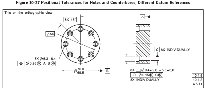
The alternative is this:
fig10-27_dcalvo.png


Which represents a method for accepting manufacturing convenience variation if the holes and counterbores are done in separate setups, such as an operator doing the counterbores by lining up a drill press by eyeball.
 
renasis,
Deriving a datum from one of your hole patterns (for using it as a reference for the other one, in your case) is usually done with the hole pattern referenced in MMB, from practical reasons (the ability to use a fixture with fixed size pins as datum simulators rather than simultaneously expanding ones). This results in datum shift (possible displacement of the controlled pattern as a group, made possible by the relative mobility between the part and the simulated datum), and that datum shift may reduce the accuracy of the alignment you want to achieve anyway. Referencing the hole pattern at RMB can allow controlling the alignment most accurately, but it also may result in technical difficulties and possibly additional cost. With the method I suggested (which is based on a Simultaneous Requirement as described in ASME Y14.5) you should be able to control the relative alignment tightly enough for most cases, by assigning the appropriate position values for both patterns, relative to the same datum reference frame.
 
renasis said:
ewh that is what I thought of doing, but wasn't sure how. Do you have example that you could share?

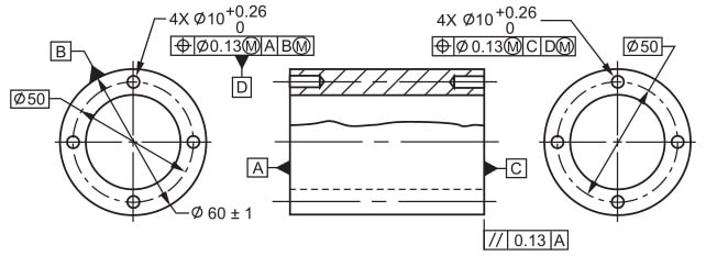
Here is the example for your reference.

2023-10-03_113216_hyuqnu.jpg


Burunduk said:
Simply control both patterns to the same datum reference frame

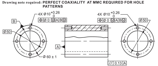
That will be a default Simultaneous Requirement on GD&T Y14.5 standard

2023-10-03_115454_q3dfp0.jpg


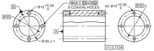
The 3rd example is exactly the same as your case, the two 4 hole patterns have different size.

2023-10-03_115752_gy7pot.jpg


Season
 
SeasonLee,
I really appreciate the spot-on examples that you often give, and this post of yours is especially comprehensive for this discussion and definitely deserves the star I gave you, just like the previous one.

Of interest is the note above the second example - "Drawing note required: PERFECT COAXIALITY AT MMC REQUIRED FOR HOLE PATTERNS". How does the source explain the reason that such note is needed there? The two hole patterns are at a Simultaneous Requirement, and both tolerances allow zero deviation from true position at MMC. Doesn't that alone impose that same condition?
 
Just for the record, in the examples given by SeasonLee, one needs to keep a few things in mind (in addition to the problematic note from above example #2):

1. There is not enough information to be able to calculate the MMB sizes of datum feature simulators B (all examples) and D (example #1).

2. In example #1, the second pattern is not only controlled for orientation/clocking but also for location with respect to the first pattern (datum feature D).

3. 8 COAXIAL HOLES definitely doesn't look right in example #3. If anything, these are 4 pairs of 2 coaxial holes, or just simply 8 holes.

 
seasonlee - the first image is a problem because the datum feature D is not defined relative to datum feature C so the virtual condition for it is also not defined for the DRF that combination is applied to.

Even if that were not the case, it is entirely possible for the pairs of holes are perfectly coaxial and the part fails the position requirement because of acceptable angularity (controlled by parallelism) from one face to the other.

That means the holes are exactly where you want and every other characteristic is in tolerance and it still fails inspection.
 
Burunduk/pmarc/3DDave

All figures come from the source of "GD&T Tips and Tools" by Genium group inc. The title is "Hole Pattern Alignment".

2023-10-04_070440_rokibb.jpg


I also have some questions about this brief note, so I will say "That [highlight #FCE94F]will be[/highlight] a default Simultaneous Requirement on GD&T Y14.5 standard" at example #2. I know that there is some information that is incorrect from the Tips and I am glad to learn some concepts from all of you on this Forum.

Season
 
Genium used to be a source of a drafting book - duplicating the basics of enough of other standards so the buyers of the Genium book would be able to avoid paying for the far more expensive primary standards. Drafters I worked with just looked for a picture or description that matched. Not sure if they licensed content.

I see nothing recent, so I suspect Genium is toast.

From 2006:

tunalover said:
I recommend the GENIUM DRM (from Genium Publishing). This was originally the GE DRM. GENIUM bought the manual from GE and has since taken over maintenance. This manual emphasizes meeting ASME Y14.100 (formerly emphasizing MIL-STD-100) and all standards reference therein (and that's a big pile of standards!).

You can buy hardcopies with a yearly update service and/or a CD containing the manual on smart pdfs (allowing searching for keywords!).

You simply can't go wrong with this. Note that GLOBAL DRM (as of last November) is no longer being maintained.
 
That first example by ewh/SeasonLee is interesting to me because I regularly work with split machined housings that have dowel pin holes to align the halves and bearing bores on each housing half. It could work quite well to use the set of dowel holes as a datum feature for positional tolerances on each bearing bore. (I need to explore this in our CMM software next.)

I think a lot of the rest of the discussion depends on whether the sets of holes are through holes or are blind/opposite holes per the graphical example. For through holes I suspect most of the issues vanish. For the blind holed examples, the example presentation creates many complications that distract from the concept of having a datum from a set of features.
 
Status
Not open for further replies.

Part and Inventory Search

Sponsor