Daniel-PRE said:
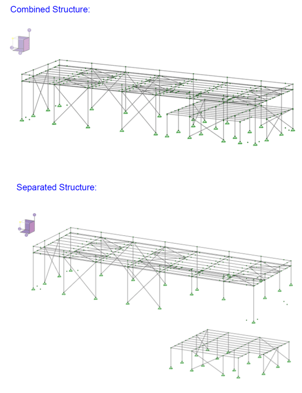
They then transfer forces (this is the two-stage analysis bit) to the braced frames of the mezzanine to get down to the foundation.
This bit sounds more like a vertical combination of lateral systems.
If treated properly as a vertical combination then it can probably work out just fine.
Here they are looking to use lower detailing requirements, on a typical 2-stage analysis building you're looking to reduce upper story diaphragm demands by not including the podium weight in the vertical distribution of base shear on the wood building.
The 'penalty' the code requires is listed in ASCE7 12.2.3.1. Your R factor on the bottom level cannot be higher than the R factor of the top level.
So in this case assuming ordinary frames.
R upper = 3.5, Cd = 3, Om = 3
R lower = 3.25, Cd = 2, Om = 3.25
Forces reacting from the upper structure get scaled by 3.5/3.25.
Seems perfectly reasonable to me to just use R=3.25 for the entire structure and do only 1 check for drift using Cd = 3.
The key distinction is the vertical distribution of base shear must include all of the weight from levels above the foundation. The upper level will see a higher proportion of base shear than the lower level. A 2-stage analysis doesn't account for this, a vertical combination of systems does.