Continue to Site

Eng-Tips is the largest engineering community on the Internet

Intelligent Work Forums for Engineering Professionals

  • Congratulations waross on being selected by the Eng-Tips community for having the most helpful posts in the forums last week. Way to Go!

two-stage analysis 3

Status
Not open for further replies.

Daniel-PRE

Specifier/Regulator
Sep 5, 2023
13
I'm reviewing a design where the engineer is wanting to use two stage analysis to get out of loading the roof with seismic weight from the concrete topped mezzanine deck. The problem is the base for the upper structure is not all at one level. This doesn't seem like the right use of the two stage analysis, but they're adamant they can use it. Am I missing something? See image below showing how they propose the analysis will work for the "upper" and "lower" structures...
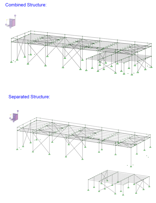

two-stage_example_ehn4vj.png
 
Replies continue below

Recommended for you

Both points taken Daniel and KootK.

If the braced frame structure is stiff enough then I could see what KootK is talking about.
But it still feels weird to me to have a dual stage structure on just a few lines of resistance.
 
I can almost get on board with the 2 stage approach because the mezzanine extends fully across the building footprint, rather than just a partial mezzanine level. But I still think decoupling loses the frame action curvature that directly influences the stresses at the joints. I suspect if you compare frame mode shapes of the decoupled model vs the coupled model, it would be quite different.

I don’t think the 2 stage approach is indefensible or totally irrational for this building, but I’m hung up on the fact that they are breaking up a continuous column moment frame member into two imaginary segments and saying they act independently. I’d at least want to see the mode shape comparison to validate the 2 stage method is still approximating the coupled response.

On driftLimiter’s last point about the few lines of resistance, maybe that could be addressed as a torsional irregularity and taking the 30% penalty on rho?


bones206 said:
...but I’m hung up on the fact that they are breaking up a continuous column moment frame member into two imaginary segments and saying they act independently

Is that what's happening here? If so, that changes things a great deal for me. This is precisely why I previously asked these questions of Daniel-PRE.

KootK said:
@Daniel-PRE: you can help us clear this up and, in the process, help us advise you better:

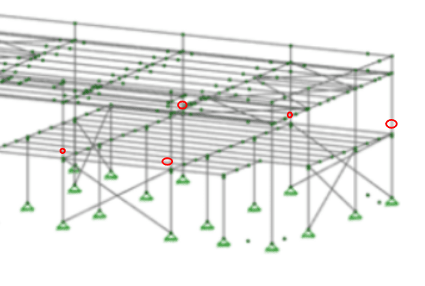
1) What kind of columns are the columns highlighted in yellow below? HSS? WF? Tapered Pre-Engineered Building?

2) What do the connections look like at the circled locations? Does anything thing about them suggest their deliberate design for moment transfer?

I've been thus far taking the EOR at their word with respect to the intent that they show in their model. If that's all bullshit, then it's a different conversation.

If bones206's read is accurate, then:

a) The PEMB end columns are seeing some serious moments at me the mezzanine level.

b) The two mezz frames resisting transverse shear must be hurting for OT unless they sit on large grade beams that span the entire building.

c) The shear anchorage of the PEMB columns behind the mezz must be working pretty hard.

I'm willing to support the telling of interesting structural stories. But not structural fairytales.
 
The bottom of the top column segments were modeled as pins, so maybe that’s also how it’s detailed. On the other hand, they are trying to avoid classifying it as a two story tall IMF, so that implies continuous columns. We are kind of guessing here without more details.
 
I'd feel better about the modelling integrity here if the combined model was showing some evidence of pins at the locations shown below. I don't know how much to read into that, however, given that I also don't see pins at the ends of the cross bracing. Perhaps these model views are at a level of detail that would not elucidate such features.

c01_v5ermm.png
 
Hard to tell since they don't have member releases turned on. I wonder if this actually is a PEMB, because it looks like they modelled the purlin lap splices.
 
The moment frame above the mezzanine is only a single story, but the structure is two story. The exception to use an OMF in SDC D and above is for single story structures, hence trying to use the two-stage which would allow the "single story structure" to be the OMF's on the whole thing and then the "two story structure" as the OCBF under the mezzanine.

I discussed with a colleague using the flexible diaphragm at the roof and analyzing frame by frame the tributary loads and using two-stage that way, but the code wants you to be analyzing the stiffness and period "of the entire structure" which would not fall into this piece-wise method.

Trying to meet the intent and language of the code is hard on this one!
 
bones206 said:
Hard to tell since they don't have member releases turned on. I wonder if this actually is a PEMB, because it looks like they modelled the purlin lap splices.

It is a PEMB, they wouldn't typically model any of it, but we asked questions and so they're enhancing their analysis in this case...
 
I think you could potentially look at it frame by frame. This is from the MBMA Seismic Design Guide (2006 version):

MBMA SDG said:
Typically in metal buildings, the interior bays are laterally supported in the transverse direction by moment frames and the end walls in the transverse direction are either braced frames or moment frames. In cases where a flexible diaphragm exists between the end walls and the first interior moment frame, separate end wall moment frame periods may be computed.

In situations where the exterior walls are hardwalls, designed to be the primary lateral force resisting system (i.e. shear walls), the value of CT and x should be selected based on the hardwall system.

What does the column splice detail look like that allows the upper half to be modelled as a separate pinned base frame?
 
Okay then...

1) I don't super love this kind of EOR gamesmanship that trades a nice, predictable structure for some bizarre code relief. That said, most of us EOR's have been in that position at some point in our careers for one reason or another. So I do sympathize.

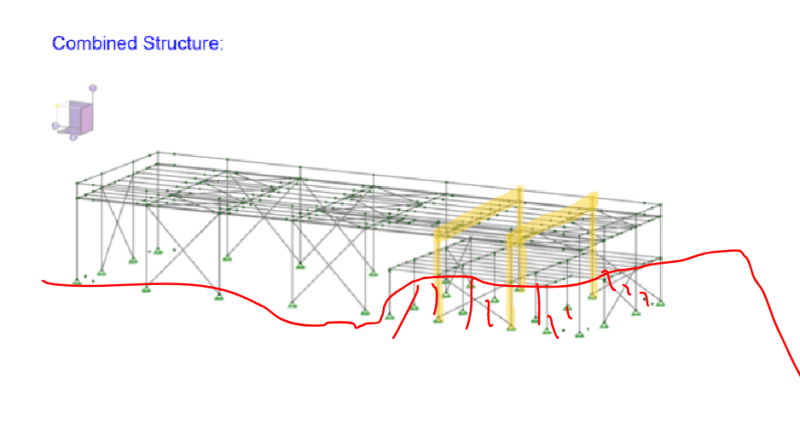
2) Done properly, I would argue that this wouldn't be much different from building a building as I've shown below where the mezzanine is replaced by a hill or something for whatever reason. Does anyone feel that we would not allow this permutation?

c01_my8mdo.png
 
I guess this is my line of demarcation: Continuous 2-story tapered column --> design as IMF and take the hit at those particular frame lines. Echoing KootK's point that that is the path to a predictable, resilient structure.

If the upper story column truly has a pinned base at the mezzanine level --> I am on board with the 2-stage approach as acceptedly rational.

Either approach I think is acceptable to analyze frame by frame as that is the traditional approach for PEMB's.
 
This book has the answers that the EOR needs to effectively design this.

Its a bit much to fully explain here but the author provides a simple means to justify that the PEMB frame is a single story OMF with a point load at the mezzanine level.

It will depend on several factors related to the dynamics of the system.

 
Thanks for all the input everyone! We ended up working with them on analyzing the modal response of the structure as they see it versus the structure if there was a hill in the middle to verify the upper structure would act similarly in both cases, then allowed the analysis as they initially analyzed it (two-stage).
 
That's an interesting outcome Daniel. Thanks for returning to the thread to let us know how it panned out.
 
@Daniel-PRE: I feel as though the EOR here owes me significant remuneration. If I post an invoice, can you pass it along for me?
 
@KootK, send it my way and I'll make sure it's sent on to the proper parties. XD
 
Status
Not open for further replies.

Part and Inventory Search

Sponsor