Continue to Site

Eng-Tips is the largest engineering community on the Internet

Intelligent Work Forums for Engineering Professionals

  • Congratulations KootK on being selected by the Eng-Tips community for having the most helpful posts in the forums last week. Way to Go!

Two Welded pipes work as cantiliver

Status
Not open for further replies.

Mohamed Maher

Structural
Dec 31, 2017
131
Dear all,
Greetings,

I have two pipes welded together as attached, they are a section of a cantilever. I can’t add one pipe only instead for architectural purpose. Is it accepted to consider them as one cross sections by getting the equivalent inertia for both pipes in resisting the major moment. Kindly advise.

Best regards,
Mohamed Maher
 
 https://files.engineering.com/getfile.aspx?folder=08495ea6-ac32-4602-a9ec-fb9bff21f993&file=Two_welded_pipes.pdf
Replies continue below

Recommended for you

Hi Mohamed Maher

I have the following questions-

1/ How long is the cantilever?
2/ Will the two pipes be welded for the whole length?
3/ What are the loads on the cantilever and what is it being used for?

I think you would be wiser to use some other structural shape like two I beams welded together, these also would be easier to set up and weld together.
I guess if you weld the two tubes together along it’s entire length, then you could argue that you would get composite action but I’m sceptical that the tubes would be straight and true over there entire length to get a consistent weld.


“Do not worry about your problems with mathematics, I assure you mine are far greater.” Albert Einstein
 
Hi desertfox,

Kindly find the reply:
long is 6m.
I can do that weld it with the full length.
its a car parking so moment around 50 knm ultimate.

I can't use any thing else than pipe because its architectural requirements.

Thanks


This is built-up section or compound section . However it is not efficient and the joint is at max. shear..You are expected to design the weld .

The weldment will be groove weld with lack of penetration. In order to calculate the thickness , assume root opening 4.0 mm and groove angle min. 15 degr. and calculate the necessary T.

My opinion...


If you put garbage in a computer nothing comes out but garbage. But this garbage, having passed through a very expensive machine, is somehow ennobled and none dare criticize it. ( ANONYMOUS )
 
Hi

I agree with HTURKAK regarding lack of penetration of the weld, essentially the weld in my eyes will be no better than a fillet weld and you never get full penetration on a fillet weld, see this link
Fillet welds fail in shear so you have to design the weld based on the throat area of the fillet, I personally think that you will have problems trying to weld two tubes in the manor shown and keeping them aligned.

I would not assume composite action due to my concerns with the welding and so I would assume that you have double the inertia of one pipe.

“Do not worry about your problems with mathematics, I assure you mine are far greater.” Albert Einstein
 
Mohamed Maher:
Your sketch shows two pipes approx. 141mm o.d. and about 6mm thick, nested one atop the other. Your welds would be something akin to flare vees or flare bevel welds. They are not a particularly good or easy to make weld, in a quality way, from a structural standpoint. You should avoid them in this application. I would use two 140 - 150mm wide by 8 or 10mm thk. bars, one each side, standing vertically. Grind or nibble a 20̊ bevel on the long, front corners/edges of these bars, with a 1 or 2mm land of sorts, on the back edge, maybe grind that a bit to conform to the pipe o.d. shape. Stand these bars vertically in your sketch, on either side of the nested pipes. The weld joints will then be at about 45̊ below/above the horiz. axes of the pipes, and you will have a nice groove weld to fill, a measurable weld throat. Draw this whole system out, to scale, to see how it works/looks. You may have to thicken the bars to get enough weld throat. You then calc. the shear flow (weld size) of these welds for your combined section. Check any punching loadings (radial loading), from the bars to the pipes, which might cause pipe buckling. The 140-150mm wide bars gets these joints high enough on the pipe shape so this shouldn’t be much of a problem.
 
I like dhengr's proposal and would have suggested the same thing if he hadn't.

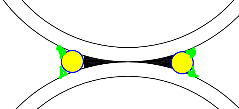
Depending on what look the architect prefers, the detail shown below may be another viable alternative to improve the welding condition.

Capture_ggiu2c.png
 
Thank you all for your valuable feedback

Now I'm thinking for other thing ..to add local weld joint like 10 cm ..and depending on theses welded parts to transfer the load from the upper pipe to the lowest one ..so that each pipe will support without need to consider them as one inertia
 
Status
Not open for further replies.

Part and Inventory Search

Sponsor