Continue to Site

Eng-Tips is the largest engineering community on the Internet

Intelligent Work Forums for Engineering Professionals

  • Congratulations KootK on being selected by the Eng-Tips community for having the most helpful posts in the forums last week. Way to Go!

Type of Contactor for Direction Change of Single-Phase IM 5

Status
Not open for further replies.

sham96

Automotive
Apr 15, 2019
35
hello everyone!

I want to change the direction of rotation (FORWARD and REVERSE) of a single-phase induction motor using two magnetic contactors. However I am confused as to the type of contactors I should use:

1. Should it be a NO or NC type four-pole contactor? (220V coil)
Photo attached below.

Sincerely grateful for any help!
 
 https://files.engineering.com/getfile.aspx?folder=f18c7670-b340-45fd-8e35-2ca5b3397e33&file=A7B7FB7C-AE70-4A63-A1D7-21C2BF6BB558.jpeg
Replies continue below

Recommended for you

Dear Mr. sham96

Q. " I want to change the direction of rotation (FORWARD and REVERSE) of a single-phase induction motor using two magnetic contactors....."
A. It is NOT possible to change the [direction of a (single-phase) motor] by inter-changing the two supply lines. Some single-phase motor windings are connected internally making it impossible, unlike a three-phase motor.
Your question whether NC or NO contactor and the attached photos are irrelevant. Take a photo of the motor name-plate including the (winding connection) and the (starter wiring), [if it is an existing F/R starter].
You would need help to look into the circuitry, if you are going to design a [new] F/R starter.
Che Kuan Yau (Singapore)
 
Dear Sir,

Thank you for your response! The Single-Phase IM is a capacitor start motor and I have attached both the motor nameplate and wiring diagram photos.

Can I wire this motor to rotate in both directions?
 
 https://files.engineering.com/getfile.aspx?folder=5facfe1c-da77-48d9-9d8b-2e1366ffadbe&file=FE8A19D6-D1FE-456A-B826-52356E0F9A18.jpeg
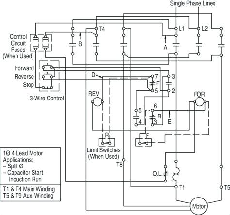
The problem is, using contactors for reversing a single phase motor is a LOT more complicated than just using a standard manual "drum switch" or "cam switch" designed for that purpose. It can be done, it's just more work than most people think is worth it for a single phase application.

Here is a wiring diagram from an OLD starter wiring diagram book for NEMA starters. I'm not sure anyone still publishes this because they ended up being so rare.
single-pha-reversing-contactor-wiring-diagram_fxhual.jpg


" We are all here on earth to help others; what on earth the others are here for I don't know." -- W. H. Auden
 
At 1/30 hp we are below industrial sizes. The maker's diagram in Sham's photo is a bit weak, the literature at shows the connections better. The maker has arranged the windings and the capacitor so that only a single lead has to move to reverse direction. In the sketches at the bottom left of the PDF, the 220v supply on the right edge of each sketch is connected to black & white for CW and black & brown for CCW.

All you need Sham is a single NO contact of your CW control from supply to white/V for CW and a single NO contact of your CCW control from supply to brown/Br for CCW. Black/Sv would be permanently connected to the other side of your supply and the motor thermal protection would be in one of the supply lines.

Any relay or switch with contacts rated for 2420v 0.5A or more would be fine. You don't even need a motor contactor if you have a thermal protector in the supply line.

Last point, you have noticed that this motor has a spring loaded brake?

Bill

edit: had omitted "for CW"
 
I've modified a few single phase motors to be reversible by installing a DPDT switch on the motor itself to reverse the leads to the start winding. That allows you to select the direction of rotation prior to energizing the motor. Once the motor is running the switch will not reverse the motor until the next start.

It can be done a couple different ways with contactors, but, as noted, it gets a lot more complicated.
 
Dear Mr.sham96,
I hope the proposed circuitry would be helpful to you
Che Kuan Yau (Singapore)


image0_znp7ti.jpg
 
Dear Mr. jraef
With due respect, your learned proposal is a beautiful circuitry suitable for "professional engineers" but NOT useful for a small motor. The cost of the components used would be more than the price of the motor.
Che Kuan Yau (Singapore)
 
See the diagram posted by Bill West.
Best to follow the manufacturers instruction.
Or RTFI.
Two contactors such as you show will work well but be expensive. There are many more economical solutions.
A two pole, double throw switch with off position will work.
See Mr, Che's diagram.

Bill
--------------------
"Why not the best?"
Jimmy Carter
 
Thank you all for your kind responses! I was in the mindset that only contactors can be used to reverse the direction of motor rotation but now I have decided to use a DPDT switch :)
Very grateful for all the help, kind regards and stay safe!
 
che12345,
That was my point, doing this with "contactors" is more complicated than it is worth, it is far simpler to do it with a manual switch made for that purpose as illustrated in your diagram, they are readily available from many sources.


" We are all here on earth to help others; what on earth the others are here for I don't know." -- W. H. Auden
 
Status
Not open for further replies.

Part and Inventory Search

Sponsor