Eng-Tips is the largest engineering community on the Internet

Intelligent Work Forums for Engineering Professionals

  • Congratulations waross on being selected by the Tek-Tips community for having the most helpful posts in the forums last week. Way to Go!

Typical detail for holes in 2-way flat slabs

Status
Not open for further replies.

ajk1

Structural
Apr 22, 2011
1,791
0
0
CA
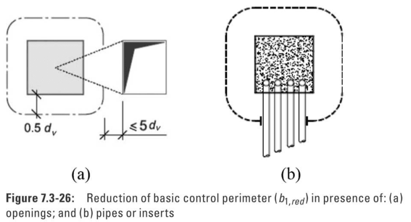
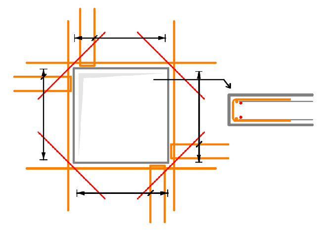
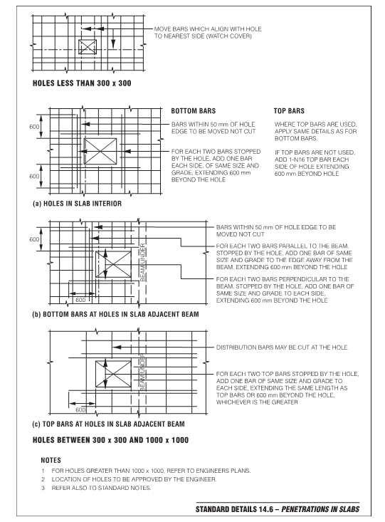
Has anyone developed a good comprehensive typical detail for holes in two-way flat slabs that are not supported by beams or walls? It would deal with added diagonal corner bars to control slab cracking emanating from the corners, bars along sides of openings, max size of openings, etc. I have seen some typ details but they seem not very comprehensive.
 
Replies continue below

Recommended for you

Also, does anyone have any rule of thumb about how far away from supporting column face, a hole though a two way flat plate or flat slab with drop panel should be so that it does not affect the punching shear stress?

Canadian Standard CSA A23.3-2014 clause 13.3.3.4 says, "When openings in slabs are located at a distance of less than 10 times the slab thickness from a concentrated load or reaction area, or when openings in slabs without beams are located within a column strip, that part of the perimeter of the critical shear section which is enclosed by straight lines projecting from the centre of the load or reaction area and tangent to the boundaries of the openings shall be considered ineffective." Most probably ACI 318 says the same, although I do not have it.


This means that for say an 8" slab and 4"drop (total= 12"), any hole closer than 10 feet away from the column support will affect the calculated shear stress. That does not seem reasonable. Any comment?

I wonder what the Australian Code says? Is Hokie66 here?

I have seen a typical detail that says that openings can be within 2 times the slab thickness. That seems too close, unless shear calculations are made. Another competitor's detail says not closer than 5 times the slab thickness. That may be a more reasonable (safer) limit, although even that would not seem to alleviate the need to check the punching shear stress based on the effect of the hole.
 
How big are your holes? Kind of a pipe diameter up to 30 cm/1 foot circular/rectangular or more of a staircase opening?
I wouldn' care that much about the former and just apply the code.

ACI says pretty much the same as CSA (10d).

Modelcode 2010, eurocode and swisscode says 5.5 to 6d distance from support face and has to be considered in the same way as CSA:
5d_pdzj44.png


If you have a drop: The codes I mentioned define dv as the slab thickness without the drop, so in your example it would be resonable to take d = 8".

However always use your engineering judgement. For small openings (< 30cm)/pipes I would go with 5d distance to the controll perimeter and reduce the perimeter, no corner bars added at all, especially in case of circular openings.

For bigger rectancular openings i would arrange some stirrups and bars along the sides and diagonal bars in the corners as you mentioned. The same you would do in walls for a window. I consider them best practice for crack control and do not really calculate them. What do you find not comprehensive?
hole_umruxb.png

For bigger holes reduce the controll perimeter as above, but you will also have to take into account the non-symmetrically shear force acting on the control perimeter. For example two column faces recieve much more shear than the others. To calculate this is a whole other story...
 
to gargarot89 - thanks for the information, particularly what Modelcode and Swisscode say.
5.5d and 6d intuitively seem much more reasonable than 10 times slab thickness.
But why does it define dv as the slab thickness without the drop? If we are calculating the punching shear within the drop, and the hole is in the drop, it seems to me that the drop should be included. If we are calculating the punching shear beyond the drop, then the drop would not be included. No?


(Please also note a small point, that "d" in CSA is not the slab thickness; it is the depth to the steel centroid, but that is a relatively minor point in this discussion).

I ask the question not for any specific project or size of opening, but to develop a "typical detail" that could be used for all jobs, to apply for all openings up to a given size...say as big perhaps as 1 m square (3'-3")

 
I have seen some discussion around diagonal bars at openings in concrete - particularly that they aren't needed, they don't provide any benefit, and in fact they are detrimental as they create a lot of bar congestion around the corners, which are sensitive to cracking.

the regular steel grid should suffice - if any more reinforcement is desired, run extra bars parallel to the opening
 
The Australian code says punching shear strength is reduced if the clear distance between the critical shear perimeter and the hole is less than 2.5*hole diameter (or hole width measured perpendicular to a line from hole to column).

The critical perimeter is half the average effective depth away from the column face.
 
to NorthCivil - thanks for that info. I too had thought of eliminating the diagonal bars and increasing the parallel to the side bars to compensate. But I seem to recall reading many years ago about research work that showed that diagonal bars were more effective in resisting corner cracking, than parallel bars. (I think it may have been in an ACI Journal. Can anyone else recall that?). I suppose it might depend on how much the parallel bars are increased. But adding corner bars is such a very common practice that I am reluctant to eliminate them because any corner cracking (which is probably inevitable no matter how it is reinforced) will be attributed to lack of corner bars and I don't know that I would want to try to defend that in court it it ever came to that. But I will give it further thought.
 
to Steve49 - thank you for that info. Is that to be taken as the greater of those 2 criteria?2.5*hole diameter (or hole width measured perpendicular to a line from hole to column).
 
I didn't explain that very well. It's 2.5*diameter for a circular hole. For other hole shapes, it's 2.5*the width of the hole, with the width measured perpendicular to the line joining the hole and column.
 
Here's the Australian detailing manual's page. The British manual is somewhat similar but calls for 45*diameter extension of the additional bars beyond the hole rather than 600mm. I think the larger of the two should be used. The Australian details are on one page so I've posted them out of convenience.

The British manual also recommends diagonal trimmers for slabs thicker than 250mm, area to be similar to the main reinforcement, subject to not causing congestion. My own view is that diagonals are good if they're in the surface layer, but if they're in the third layer from the surface they're obviously far less effective and just contributing to congestion. Trimmers in the main directions can do the same job but need twice the steel than diagonals. The area of trimmers should probably be related to the slab depth as the tensile force required to cause the crack is larger in a thicker slab.

Aus_Slab_Pennos_br8z4q.png
 
Since diagonal bars are there primarily to resist shrinkage, wouldn't they also be effective even if located mid-depth of the slab, assuming shrinkage stress is uniform throughout the slab depth?
 
I don't usually use diagonal bars for slab or wall openings. They just add to the congestion in high stress areas.

If you need more rebar, add to the bars at the sides of the opening (increase bar size).

Dik
 
steve49 said:
Trimmers in the main directions can do the same job but need twice the steel than diagonals.
How did you arrive at needing twice the steel? Is that based on a calculation, or a rule of thumb, or accepted practice?? If I adopt this, I just want to know its basis. Thanks.
 
steve49 said:
Trimmers in the main directions can do the same job but need twice the steel than diagonals. The area of trimmers should probably be related to the slab depth as the tensile force required to cause the crack is larger in a thicker slab.

When you say trimmers need twice the area of steel as diagonal bars, do you mean that if there are 2-15M diagonal bars (= 2 x 200 = 400 mm²) crossing a corner of the opening, that they would be replaced by 2-15M trimmers in one direction and 2-15M in the perpendicular direction, for a total of 4-15M?
 
Yes, that's what I meant but was thinking of the case of many bars at regular spacing. Say you have 10mm bars at 100mm centres in the x-direction, or 10 bars per metre. Cut a section at 45 degrees where a crack is forming. Over 1m of the 45 degree section, you have 7.07 bars (cos 45 degrees), with the maximum force perpendicular to the 45-degree section being (cos 45 degrees)*yield strength due to the bars being at an angle to the section. So the strength per unit length on the 45-degree section is (cos 45)^2 = 0.5* the x-direction strength. Repeat for the y-direction.

Trimmers however are a single bar (or a bundled pair acting like a single), so one of those (cos 45) doesn't apply. That calculation was for strength though. For crack control, maybe it gets reintroduced somehow for equal crack width; I haven't thought that through. It's not an exact science though. I'd just put about whatever diagonal trimmers you were thinking of in each of the x & y directions.

My reason for wanting the bars near the surface rather than at mid-depth is that I don't trust shrinkage to be uniform. It will find a way to vary when you least want it to and the strain gradient will increase the crack width at the surface. There are a lot of reasons why shrinkage mightn't be uniform such as different exposure top and soffit, different finishing (soffit compacted against forms but surface trowelled), water gain/bleed at the top etc.
 
Status
Not open for further replies.
Back
Top