Eng-Tips is the largest engineering community on the Internet

Intelligent Work Forums for Engineering Professionals

  • Congratulations waross on being selected by the Tek-Tips community for having the most helpful posts in the forums last week. Way to Go!

Typical warehouse connection detail 1

Status
Not open for further replies.

dsdt

Structural
Jan 18, 2021
14
0
0
AU
Hi,
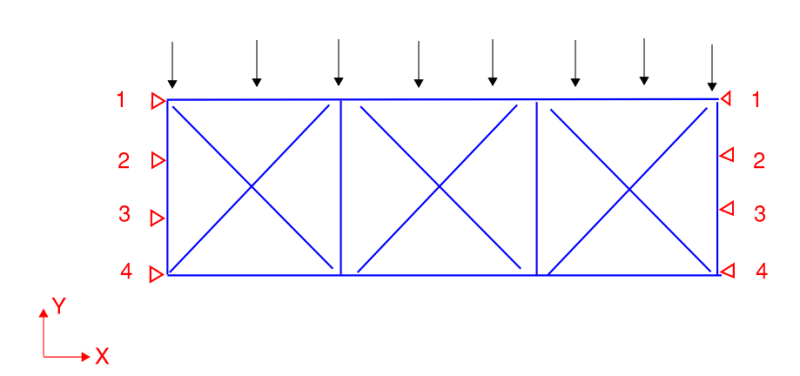
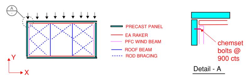
The way I analyze this warehouse subjecting to wind in say Y direction is using Y direction walls as supports and the roof structure as a truss to transfer the lateral loads to these walls. I would expect large reaction at end due to its span. Now my question is, will the very first bolt for pfc wind beam to wall sufficient to carry this load? (refer to the detail A below. raker-wall, raker-wind beam connection etc are not shown). I have done the check and find the capacity lower than design reaction but I have seen this detail being used quite a lot. So how do you normally detail this?

12_lfhpjw.png
 
Replies continue below

Recommended for you

I'd typically see people sharing the load evenly between all bolts between steel and wall.

The thing to remember with bolting in this configuration is that even if the first bolt fails the concrete due to the smaller edge distance and possibly carrying more than its fair share of the force, the load just redistributes to the next 2/3/4 bolts, etc as a group which have more capacity and so forth due to larger edge distances.

If you wanted to isolate the first bolt, for example if it had a very small edge distance and you were worried about the edge breaking out, you could provide a slotted hole in the steel.
 
Can you please explain why loads can be distributed to the other bolts? I would expect the reactions go to the outmost bolts only.
My analysis model is as follow. Say I have 4 bolts along Y direction wall on each side. Now I put Y translation restraints for all of them. The analysis results will show that the reactions go to the outmost bolts only. (ie. node 1s as shown below) So if the first row of bolts fail then the loads go to the second row, which cause them fail too and then go to the third... causing them all fail? I don't quite understand how these bolts can work together to resist the loads? Can you explain? Thanks.
22343_hovvbl.png


I find the bolt fail even for its strength not just because of breakout failure (with long span, the end reaction can go to 100kN and above) unless my assumption (- only the outmost bolts take the loads) here is wrong. So if the first row fails, the second row will take the load and fail too.
 
Your support assumption is a little incorrect here. I think if you modelled as 4 Y direction stiff springs it's more realistic. Infinitely rigid supports are not realistic (or possible).

The load can still travel down the steel to the other bolts before transferring to the wall.

The true load distribution is dependant on a lot of factors like relative stiffnesses, bolt hole clearances, etc, factors that are hard to rationally account for in day to day design. But I'd reason that most people would make the assumption that the bolts share load more or less evenly in this or similar situations. Which an analysis with springs would show you.
 
I'm wondering if you are talking about X- or Y-direction load. I think it should be clear that the Y-direction load can be shared in shear by all the bolts connecting the pink ledger to the wall. For the X-direction thrust load, you may be thinking that would be taken in tension by one of the bolts holding the pink ledger to the wall, but that can be resolved either through shear by all of the bolts holding the red ledger to the wall, or by the red ledger acting as a continuous tension member connecting both ends of the truss. In this way, the truss model that you are using matches the more common (in my experience) deep beam model of the diaphragm with a chord member on the top and bottom.
 
OP said:
Can you please explain why loads can be distributed to the other bolts? I would expect the reactions go to the outmost bolts only.

1) I certainly get where you're coming from with this concern. Even within steel to steel bolted connections, there are sometimes limits on how far back you can assume a uniform force distribution without having to take capacity hits for reduced connection efficiency. Here, axial elongation of your wimpy deck edge member will surely make it unrealistic to share the load back over 30', 40' etc. I try to get this kind of thing done over a distance in the 4'-8' range if I can. Like Agent666 said, though, this isn't something that's very easy to parse out with any accuracy in day to day work.

2) I suppose that one could fairly easily calculate axial elongation along the length of the deck edge member and then compare that to hole tolerance to try to come up with a reasonable distance for load distribution. One wrinkle with this is is that, similar to column base plates, you'll likely not be able to control which fasteners get installed right snug to the bolt holes and which have a gap from the outset. This situation, with post installed anchors, is better than it would be with base plates because you're unlikely to be using oversized holes.

3) The distribution question makes me long for connections with ductile governing failure modes. Unfortunately, that tends to be a pretty tall order in these kinds of situations.
 
Errata: I was assuming a fairly small deck edge member (angle etc). If your PFC wind beam thingy is actually a more substantial member, then I'd be comfortable with a longer distribution length as axial strains may be unlikely to amount to much of significance in that case.
 
Status
Not open for further replies.
Back
Top