Continue to Site

Eng-Tips is the largest engineering community on the Internet

Intelligent Work Forums for Engineering Professionals

  • Congratulations KootK on being selected by the Eng-Tips community for having the most helpful posts in the forums last week. Way to Go!

Unbalance Protection via 50N, 50G and 50GS 5

Status
Not open for further replies.

Ali-rashid

Electrical
Oct 25, 2017
19
I know ANSI46 can detect unbalance conditions very well but I am trying to understand the unbalance protections for a distribution transformer via 50N, 50G and 50GS.
Our network uses delta/grounded wye transformers, so the protection scheme would be as below based on IEEE 242 book :
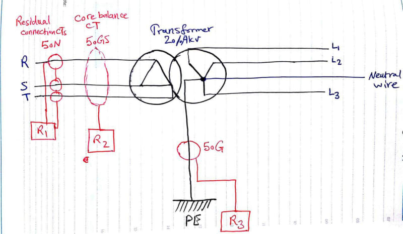
photo_2019-03-06_12-52-02_qy0mwk.jpg


Considering this is a public transformer with a lot of single phase load (or any loads which may cause unbalance) connected in secondary I need some clarification for protection in unbalanced conditions.

1- In case of unbalanced loads, which of the protections (R1,R2,R3) can detect it and why?

2- In case of unbalanced loads, If there was no Neutral wire in secondary but the star is grounded, which of the protections (R1,R2,R3) will detect it and why?

3- In case of unbalanced loads, if the star is not grounded (there is no R3 protection relay as a result) but the neutral exists, which protections (R1,R2) will detect it and why?

Thanks all
 
Replies continue below

Recommended for you

Where is the load? Normally it would be on the wye side as would R1 and R2. On the delta side, with the source on the wye side, neither R1 nor R2 will see anything and R3 will respond to faults on the source side. If the source is on the delta side R1 and R2 will only see faults in the transformer and will be blind to faults on the wye side.

With the source on the delta side and with R1 and R2 moved to the wye side, all three see the same faults. R2 would be rare on solidly grounded systems but would replace R1 on high resistance grounded systems. R3 is likely to be implemented in the transformer protection while R1/R2 could be in either the transformer or the feeder protection or both.
 
I guess your source is on delta side and load on star side.
The protections you indicated are meant for detecting earth fault. None of them can detect unbalance in the load.
If you have a relay that measures discrepancy in the three phase currents, whether on star side or delta side, this can indicate unbalance in load.
 
I think you would have to do an assessment to determine how much zero sequence current occurs under normal conditions and make sure your pickup is above that with margin. If you have a lot of load diversity and it was balanced as much as possible, you usually should have that much in comparison to fault current. When I see a lot of single phase loads, that screams at me that I am going to be doing phase protection.

------------------------------------------------------------------------------------------
If you can't explain it to a six year old, you don't understand it yourself.
 
Hello

I would like to know ,how CBCT at delta side of the transformer and source in same side, will differentiate that the output of CBCT is only due to fault or unbalance in the load currents.
because we have an issue that CBCT always gives some leakage output even all phases are healthy. We would like to know ,is it due to unbalance or CT error, unfortunately we don't have any test to carryout the CBCT performance test.
Also how the assessment can be done to know how much Zero sequence currents occurs under normal conditions in a power system. Is there any specific set of tests available for this ?
 
The source is on the delta side. The problem is that my field experience was that the unbalance load cause the relays to see currents and operate depending on pickup value. I was wondering if existence of neutral wire and a grounded star would make a path for the unbalanced current to go out of the three phase system and this way the protections would act? Is this reasoning right?

davidbeach are you sure about this: "If the source is on the delta side R1 and R2 will only see faults in the transformer and will be blind to faults on the wye side." Do you mean that that R1 and R2 are only blind to unbalanced faults or blind to all faults including a phase-ground fault??
 
Blind to all wye side faults. Both connections only respond to zero sequence current and nothing on the wye side can cause there to be zero sequence current on the delta side.

R1 and R2 can both be incorrectly connected and respond to things they shouldn’t. The most common incorrect installation involves having the cable shield current being measured. If applied to shielded cable the shields need to be brought back through the CT to cancel out and not provide false indication.
 
None of them can detect unbalance on the load side!
On the feeder side to load, you need to have a full set of protections i.e. 50N/51N and also 50G/51G (ground/sensitive earth fault). 51N shall have a proper coordination with both upstream (incomer)& downstream (outgoing feeder to load).
If the relay you are using has a specific negative sequence overcurrent protection(50I_2 and 51I_2) then it recommend to use them..
 
R3 could be used to detect unbalanced loads and ground faults, if it were corrected to connect the neutral to the XO bushing. That is assuming the CT used is under the oil of the XO bushing.

R1 & R2 are used for transformer fault detection.
 
Thanks every one. Your comments helped a lot understanding the scheme.
I have one last question. Can R1 or R2 detect any ground faults on primary Delta windings or lines (the distance between CTs to Delta winding) considering that the primary is ungrounded?
 
Status
Not open for further replies.

Part and Inventory Search

Sponsor