Continue to Site

Eng-Tips is the largest engineering community on the Internet

Intelligent Work Forums for Engineering Professionals

  • Congratulations KootK on being selected by the Eng-Tips community for having the most helpful posts in the forums last week. Way to Go!

Unbalanced Delta Delta Transformer Load Calculation 3

Status
Not open for further replies.

SouthSide08

Electrical
Apr 4, 2017
11
I am trying to solve line currents for a delta delta transformer using nodal analysis but couldn't arrive with the correct answer. The simple way I have done this before is to distribute kVA loads to individual phases then divide by the Voltage / Sqrt 3. Say we 3kVA load on phase AB, 4kVA on BC and 5kVA on AC. The system is Delta-Delta 2400 - 240Vac. What I would do is do a schedule and get the total kVA per phase. Phase A = 4kVA; Phase B = 3.5kVA; Phase C = 4.5kVA. I would then divide each phase by 240/sqrt3 to get the individual line currents which result to IA = 28.87A IB=25.26A IC=32.48A

I believe this is a correct and simple method but I would like to solve this using nodal analysis to get the phase angles on the individual currents as well. A spreadsheet mentioned on thread238-156846 has an answer for this type of loading but the link mentioned on the thread does not work anymore. I was hoping somebody can give me the spreadsheet or if not help me on how to solve this using nodal analysis. Also interested on how to do the calculations when dealing with mid-tap single phase transformers. Appreciate any comments and advice on this matter.

Respectfully.
 
Replies continue below

Recommended for you

I can give you a word description.
Use three equal transformers.
A single phase load on a delta transformer will cause equal currents and equal KVA in all three phase windings.
For the instance of single phase loads on A phase you may consider B phase and C phase to be an open delta transformer bank.
This will form a virtual single phase transformer on A phase. If you calculate the regulation and terminal voltage of the virtual transformer you will find it to be identical to the real A phase transformer.
So, Put a 10 kW, unity load on A phase and it will split equally and the A phase winding will carry 5 kW and 5 KVA.
The virtual transformer will have equal current and will supply 5 kW.
Here's where it gets interesting:
B A phase supplies 5 KVA, B phase supplies 5 KVA and C phase supplies 5 KVA.
But that is 15 KVA for a 10 KVA unity power factor load.
The explanation is that one phase is 50% leading and one phase is 50% lagging.
So B phase and C phase each supply 2.5 kW but each supply 5 KVA.
Now start drawing vectors.
Each single phase load will cause equal currents in phase with the load in each phase winding.
If you are good with vectors you can plot the current for each phase load on all three phase windings and then resolve the vectors.
Epete may have a mathematical solution.

Bill
--------------------
"Why not the best?"
Jimmy Carter
 
You need a Microsoft Excel workbook.
At first the equations are known[index c it means " complex number"]:
IAc=IABc-ICAc in complex it will be: IAc=imsub(IABc,ICAc) etc.
IBc=IBCc-IABc
ICc=ICAc-IBCc
The known currents in complex:
IABc=complex(IAB*cos(a),IAB*sin(a)) ; a=0+acos(pfab) where pfa=power factor of IAB current [typical].
IBCc=complex(IBC*cos(b),Ibc*sin(b)) ; b=-2*pi()/3-acos(pfb)
ICAc=complex(ICA*cos(c),ICA*sin(c)) ; c=-4*pi()/3-acos(pfc)
IAc=imsub(IABc,ICAc)
IBc=imsub(IBCc,IABc)
ICc=imsub(ICAc,IBCc)
In order to find the absolute value you'll do:
IA=imabs(IAc) [typical]
and the IA pf as cos(fia) where fia=imargument(IAc)
If pfa=pfb=pfc=1 then IA=29.16 A ;IB=25.34 A; IC= 32.5 A
 
Thank you for the comments!

I put it in excel and I got the following:
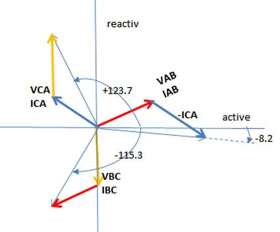
IA = 29.16 <8.21
IB = 25.35 <115.28
IC = 32.54 <-123.67

To get the "<" Angle
I get the imaginary and real individually from IAc as
Real: =IMREAL(IAc)
Imaginary: =IMAGINARY(IAc)

and then the angle will be "=DEGREES(ATAN2(Real,Imaginary)"

I think I got this correct including the angle?? for the voltage I used the following conventions:
VAB = 240<30
VBC = 240<-90
VCA = 240<-210

I can double check using SKM Unbalanced Load Flow...

Another mystery to me is how do we solve line currents for multiple single mid-tap transformers connected to a 3-phase System. How do we solve the individual Line Currents on the primary...

Easy to get the Primary Line Currents from the individual mid-tap single phase transformers. But in order to add everything correctly you have to know to know the correct phase angles...
 
The angle absolute values are correct but the sign is opposite.

Delta_unbalance_loads_isd2re.jpg
 
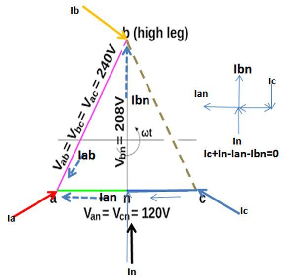
If” line currents for multiple single mid-tap transformers” it is about open-delta with high-leg 240/120/208 V then the equations are as following:
[Usually what is known are the entering currents :Ia,Ib,Ic and In and has to be calculated Iab,Ian and Ibn.]
in point a: Ia+Iab+Ian=0
in point b : Ib+Ibc-Iab+Ibn=0
in point n : Ic+Ibc+In-Ian-Ibn=0
Let’s put Ibc=0 and Iab=x;Ian=y;Ibn=z
Then:
Ia+x+y=0
Ib-x+z=0
Ic+In-y-Z=0
open_delta_transformer_bk6og8.jpg
 
Sorry. Since I forgot z in the last equation the result is wrong. It seems it is no solution in this way.[blush]
 
A suggestion:
1. The positive sequence currents should be easy to plot. That leaves the single phase currents.
2. Add a single phase current equal to the single phase load on A-B phase and in phase with A-B. This current may now be combined with the positive sequence line currents of Line A and line B.
3. Now consider the current on C phase.
This will be the same as a current of 50% of the single phase load current connected across an open delta. Solve for 50% of the load on the common leg of an open delta and you have your three line currents. Now combine the solution with the positive sequence current on C phase. The A-B component of this current has been considered and combined with the A & B currents in step 2.

For a 10 Amp load:
Line A and Line B, 10 Amps in phase with A-B.
Line C Solve for the current on line C with a 5 Amp load across an open delta at A-B.
I hope this helps.
Each single phase load may be resolved and combined with the positive sequence current in this manner.
I hope this helps.


Bill
--------------------
"Why not the best?"
Jimmy Carter
 
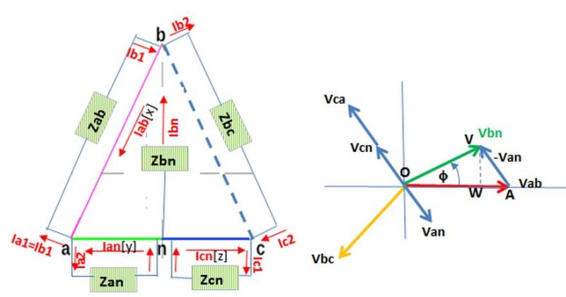
Actually we don't know IA,IB,IC and IN but Ia1=Ib1,Ib2=Ic2,Ia2,Ic1 and Ibn according the
attached diagrams:
open_delta_transformer_NEW_yksdyt.jpg

In this case it is possible to find Iab[x] , Ian[y] and Icn[z] as following[neglecting the voltage drop in the transformer windings]:
Ia1=Ib1=Vab/Zab Vab=240<0
Ia2=Van/Zan Van=120<-60
Ib2=Ic2=Vbc/Zbc Vbc=240<-120
Ic1=Vcn/Zcn Vcn=120<-240
Ibn=Vbn/Zbn Vbn=208<30
In order to calculate Vbn:
VW=120*sin(60)=103.9
OW=240-120*cos(60)=180
OV=SQRT(VW^2+OW^2)=207.8
=asin(VW/OV)=30
Iab[x]-Ia1-Ia2+Ian[y]=0 in point a
-Iab[x]+Ib1+Ibn-Ib2=0 in point b
Icn[z]+Ic2-Ic1=0 in point c
then:
Iab[x]=Ib1+Ibn-Ib2
Icn[z]=-Ic2+Ic1
Ian[y]=Ia1+Ia2-Iab[x]
It is a very sophisticated way, indeed, so I think the waross way is preferred, any way.
 
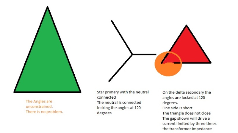
In the sketch, the green triangle shows a delta:delta or a star delta with a floating neutral. The voltage is low on one phase. The phase angles adjust to compensate for the uneven voltages.
The second sketch shows a star connection with low voltage on one phase.
The neutral is connected and this locks the phase angles in at 120 degrees.
One side is short on the delta secondary.
STAR_DELTA_jcgtpz.jpg

A couple of effects when a four wire wye:delta is used on a distribution circuit.
If one primary phase is missing, the bank will back feed that phase.
If two primary phases are missing, the two open phases will be back-fed with approximately 50% voltage. On a mixed, industrial and residential circuit, this kills refrigerators and freezers.
A line to line short will be back-fed and the fault current will be twice the expected current.
When I had responsibility for the small system it took me a couple of years to get rid of the star delta transformer banks.
Once the star-deltas were gone, there were no more refrigerator burn outs in the community.


Bill
--------------------
"Why not the best?"
Jimmy Carter
 
Thank you waross for your information. I have never used a delta open transformer and I never knew what it was used for. So many rated voltages, so dangerous in the event of a fault .My interest was purely theoretic.
 
I inadvertently posted the drawing in the wrong thread. However it is not wasted here.
A single phase load on a delta transformer winding is supported by equal currents in all three windings equal to 50% of the load current.
In the case of a single phase load, the KVA loading on the transformer bank is 150% of the load KVA.
Example:
"A" phase kW = 50%, KVA = 50%, PF = 1.0
"B" phase kW = 25%, KVA = 50%, PF = 0.5
"C" phase kW = 25%, KVA = 50%, PF = 0.5
When considering single phase loads on a delta bank from A to B, you must consider the current in C phase.
It may be interesting to look at the thread that this post was intended for. Neutral Earthing in Solar Transformers.
The information in regards to wye:delta banks may be useful.
BTW I spent some years in an area where the four wire wye:delta connection was common.
It was common to see one fused cut-out hanging down on wye:delta banks. The bank would be functioning as an open delta with one transformer energized by a back feed but not connected to the primary circuit. Most of the problems with unbalances went away and everything worked fine with two transformers. forming an open delta.
The four wire delta connection was also common with fairly large single phase loads on one phase.
You fellows are much better with the math than I am, but I have some years of hands on experience with deltas and single phase loading.


Bill
--------------------
"Why not the best?"
Jimmy Carter
 
Thanks Waross and 7anoter4! Very useful information definitely! Yeah me either haven't really used Y-High leg delta myself. I have seen some of Client's specs that this is not to be used anymore. I thought it was just because it is too confusing, but good to know what the other risks and effects are!


I am not going to put my brain through the strain of figuring out everyone's logic, but I see a basic problem statement error that makes this difficult for me:
In a delta system, loads are phase to phase, yet the problem starts my mentioning KVA on a single phase basis (phase A = ##kVA, phase B = ##kVA, phase C = ##kVA). These would need to be restated in terms of phase to phase kVA, and then a power factor. Since the loads are unbalanced, and no zero sequence load is possible in a delta system, it follows that the power factor of each load cannot be the same or the current cannot sum to 0. I would need the power factor of each load to find the answer.

A matter sort of hinted at in the answers is that for a delta delta xfmr, nodal analysis cannot solve for current inside the delta without adding an additional equation saying Ia+Ib+Ic inside the delta = 0. On paper, there could be a ton of circulating current in the deltas that never shows up in the lines.

J. Horak, P-R Engineering, Colorado
 
Status
Not open for further replies.

Part and Inventory Search

Sponsor