Eng-Tips is the largest engineering community on the Internet

Intelligent Work Forums for Engineering Professionals

  • Congratulations waross on being selected by the Tek-Tips community for having the most helpful posts in the forums last week. Way to Go!

Unbend Routing tube

Status
Not open for further replies.

NutAce

Mechanical
Apr 22, 2010
1,192
0
0
CH
Hello guys,

I have an interesting issue...

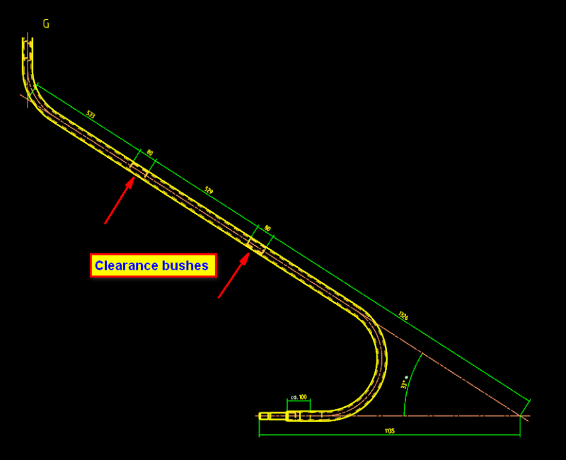
I am looking for a way to unbend a routing tube. The tube, in it's bent state, has clearance inserts to hold an inner tube in it's place.
These inserts need to be welded in the pipe before it is bent.
I would like to know the exact positions of those inserts in the unbend position. I only have the dimensions of the pipe and it's inserts after it is bent.

Any ideas? As far as I know there is no way to automatically unbend a routing tube.

Pipe_Bent_o4yhsg.png


Ronald van den Broek
Senior Application Engineer
Winterthur Gas & Diesel Ltd
NX9 / TC10.1.2

Building new PLM environment from Scratch using NX11 / TC11
 
Replies continue below

Recommended for you

Hi Ronald,

I bet you don't want just a standalone model of the straight pipe - it all has to be linked together, right? If not, measure the entire bent tube centerline arc length and draw a straight line that's equal to that overall arc legnth. If you must link together, you'll have to cut the bent ends off then add the straights back on where the bends started/ended....unless there's some unbending technique out there of which I'm not aware.

Tim Flater
NX Designer
NX 9.0.2.5 Win7 Enterprise x64 SP1
Intel Core i7 2.5GHz 16GB RAM
4GB NVIDIA Quadro K3100M
 
Xwheelguy said:
If not, measure the entire bent tube centerline arc length
That was my first thought as well. However, the measure length doesn't accept the selection of centerlines...

Ronald van den Broek
Senior Application Engineer
Winterthur Gas & Diesel Ltd
NX9 / TC10.1.2

Building new PLM environment from Scratch using NX11 / TC11
 
Not that I know much about NX Routing but how was the routing path defined and what are those orange-ish colored curves in your image? If that is a dead end, can you not extract the centerline of the tube somehow? If all else fails, draw the straight sections and add the bends with radii. Once you have the curves in there Measure Cure can be set to follow the fillets and measure the full centerline.

We make all kinds of tubing and don't mess with routing - just draw the centerline path and use Tube command...add sizings, etc. then Shell for wall thickness unless we have the rare occasion where we can define wall thickness with the Tube In & Out Diameter.

Tim Flater
NX Designer
NX 11.0.1.11 MP4
Win7 Enterprise x64 SP1
Intel Core i7 2.5GHz 16GB RAM
4GB NVIDIA Quadro K3100M
 
Those orange-ish colored curves are called Centerlines :)
We can measure the stock lentgh but then we need to divide it at the positions of the bushes. (might be the best solution)
Drawing the strait sections and Radii defeats the purpose of using routing of course. So that will not be an option.

Ronald van den Broek
Senior Application Engineer
Winterthur Gas & Diesel Ltd
NX9 / TC10.1.2

Building new PLM environment from Scratch using NX11 / TC11
 
NutAce said:
Those orange-ish colored curves are called Centerlines :)

I know that - but I have no idea if I'm looking at a Sketch which might have some useful centerlines or a Drawing - my mindreader is in the shop this week ;)

Was just thinking that if there were curves anywhere representing the centerlines that they would be useable somehow. Not sure why you need to omit the bushing areas, they shouldn't affect the length of the tube, just be holes added, obviously. I understand that drawing the curves by hand defeats the purpose of using Routing, but it would work nonetheless, which beats where you're at now.

Tim Flater
NX Designer
NX 11.0.1.11 MP4
Win7 Enterprise x64 SP1
Intel Core i7 2.5GHz 16GB RAM
4GB NVIDIA Quadro K3100M
 
Xwheelguy said:
my mindreader is in the shop this week ;)
lol...
Real centerlines.
There are curves present however. Coming from routing. I can use the path curves indeed and split them at the point of where they cross the bushing areas and measure the length after that.
Looks like this would be the safest bet.

Ronald van den Broek
Senior Application Engineer
Winterthur Gas & Diesel Ltd
NX9 / TC10.1.2

Building new PLM environment from Scratch using NX11 / TC11
 
Status
Not open for further replies.
Back
Top