Continue to Site

Eng-Tips is the largest engineering community on the Internet

Intelligent Work Forums for Engineering Professionals

  • Congratulations waross on being selected by the Eng-Tips community for having the most helpful posts in the forums last week. Way to Go!

Unbraced column effective length 3

Status
Not open for further replies.

struc_eng

Structural
Mar 24, 2017
11
Hi all,
I recently came across a question about column effective length in unbraced multi-frame system.
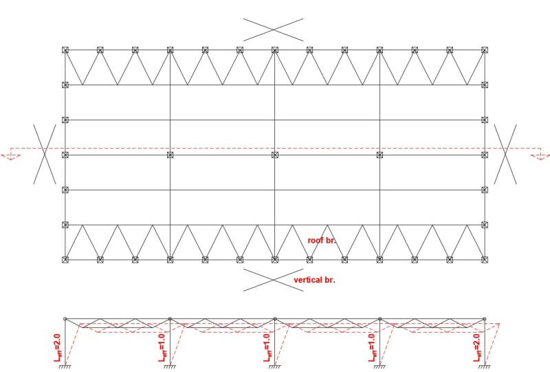
Building has a vertical wind bracing in all four planes and triangle bracing system in roof only on two opposite sides. Section view which describes situation is something like in attached picture. Columns are fixed with hinges in connection with trusses. In my opinion in direction where is no roof bracing column effective length is as fixed with free end (Leff=2.0). But what happening with columns in middle spans, Leff should be the same as for external columns or it's 1.0 ? Is there any reference to normatives ? Thank you and any comments are welcome.
 
 https://files.engineering.com/getfile.aspx?folder=2d421ce1-a8f9-48af-b67d-934745b32cd4&file=eff_l_1.jpg
Replies continue below

Recommended for you

All would have K=2.0. Do the columns needs to be fixed if you have bracing in all four planes?
 
@Canwesteng
Thanks for comment.
Project is already done by third party, we just have discussion in our company.
Columns are precast, fixed with four anchor bolts, is it 100% rigid, i'm not sure and it's another topic.
Regarding effective length, i also think that there must be 2.0 for all columns.
But if you look to this differently, for example if you have diagonal bracing between columns in first span, than all the rest columns will be with length factor 1.0 right ? So if we assume that first column is like a stiffness (bracing) element with 2.0 why can't others be 1.0 ? [pipe]
 
Sorry, I assumed this was steel. You would have to make a judgement call on the stiffness of the outer columns vs the inner columns. I'm not sure if ACI allows direct analysis but that would be the way to go if it were a steel structure.
 
The overwhelming majority of gravity columns in conventional buildings are assumed to have lateral support at all diaphragm levels, including the roof. So K=1.0+/- for the gravity columns. I'd expect that to be the case in your situation as well but, without more information it's hard to say.

1) In your region, is it common to use the roof deck as a horizontal diaphragm?

2) I'm not familiar with "triangle bracing" unless you simply mean the formation of a horizontal, concentric-ish truss in the plane of the roof.

3) Can you post a sketch of your roof plan showing the bracing that exists?

OP said:
So if we assume that first column is like a stiffness (bracing) element with 2.0 why can't others be 1.0 ? pipe

You can do that so long as your P-delta evaluation of your lateral load resisting columns accounts for the destabilizing contribution of all of the lean-on, gravity only columns.


eff_l_2_t3uslu.jpg
 
Yes, forgot to mention roof has covered with bearing sheet, but it's not calculated as diaphragm.
 
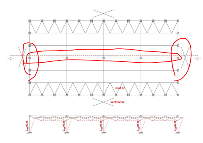
If there's no analytical diaphragm and everything is pinned connections, then I would say that the columns circled below cannot derive lateral support from the roof diaphragm. Frankly, it strikes me as an error in the original design not to have horizontal bracing running across the short dimension of the building as well.

C01_v8d0y4.png
 
kootk said:
If there's no analytical diaphragm and everything is pinned connections, then I would say that the columns circled below cannot derive lateral support from the roof diaphragm. Frankly, it strikes me as an error in the original design not to have horizontal bracing running across the short dimension of the building as well.
100% agree with this assessment.

I'll also add that the roof bracing seems quite unconventional and an inefficient way to go about transferring the lateral load the the outside braced wall. But maybe there is a reason for keeping the centre of the roof free from bracing? (I've certainly done that sort of approach on one side for floor bracing when I have multiple penetrations and don't want to rely on a metal floor as a diaphragm.)

struc_eng said:
So if we assume that first column is like a stiffness (bracing) element with 2.0 why can't others be 1.0 ?
That assumption would be wrong.

Calling the first column a stiffness (bracing) element doesn't make it one. It does not have the lateral stiffness required to make it a bracing element. Even if it had moment connected ends it still wouldn't be stiff enough to sufficiently brace the other columns against sway.

What matters in determining effective length is the STIFFNESS of the lateral restraints against sway.


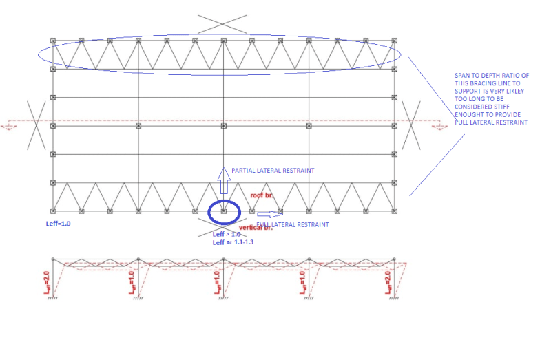
Oh and one more thing. Even your centre columns in the x axis don't seem to have full lateral restraint. The roof bracing is unlikely to be stiff enough to provide the restraint necessary. I say this based on my experience of using similar bracing arrangements and calculating the buckling effective length. This is likely a non issue unless you are living on the edge with these columns.
temp_sbheys.png
 
Thank you all for comments! I agree and most likely would also add roof bracing across the middle of the building,
and also on short sides, if i designed it myself. As you pointed out there are several questionable solutions in design,
but main focus is on middle columns. In general in situation as it is, for building to function properly all middle columns must be designed
with effective length factor equal to 2.0, which leads to more reinforcement and more stiffed cross-section. Alternatively 3D FEM calculation
can be a solution to determine exact effective length as it is according to scheme. Don't know is it even possible, no experience with this.
Can you agree with my judgments ? [smile]
 
There is an excellent blog article of how you can back calculate the effective length of a column using buckling elastic analysis.


However you still need to work or your true lateral restraint for those centre columns. I suspect your lateral stiffness here is quite low given you only have a roof diaphragm supported with trusses. Calculating this would be quite hard because alot depends on the connections and the roof diaphragm itself.

I personally would be assuming left of 2.0. If you are chasing a reduction you might get more luck from reconsidering your assumption of a pinned base connection. Most like you would have partial fixity here which would reduce Leff.

But again quantifying this can be a challenge, but likely less of a challenge than the above.
 
If this was a project in my region, and I was seeing it fresh, I would assume that:

1) The designer used the diaphragm to brace the column tops in the left right direction. At a 1:2 diaphragm aspect ratio, this makes a ton of sense if your diaphragm has any shear capacity at all.

2) The horizontal trussing that is in there is to add a little more diaphragm confidence where the aspect ratio would have flipped to 2:1.
 
human909 (Structural)22 Sep 22 19:52 There is an excellent blog article of how you can back calculate the effective length of a column using buckling elastic analysis. [URL unfurl="true" said:
https://engineervsheep.com/2019/buckling-analyses-...[/URL]]
Ok, sounds good i'll take a look. Thanks [thumbsup2]
 
Can the decking be used as a diaphragm? Small wind exposure and greatest depth?

So strange to see the singularity approaching while the entire planet is rapidly turning into a hellscape. -John Coates

-Dik
 
kootk said:
If his was a project in my region, and I was seeing it fresh, I would assume that:

1) The designer used the diaphragm to brace the column tops in the left right direction. At a 1:2 diaphragm aspect ratio, this makes a ton of sense if your diaphragm has any shear capacity at all.

2) The horizontal trussing that is in there is to add a little more diaphragm confidence where the aspect ratio would have flipped to 2:1.

That would make sense IF you could use the roof as a diagram. Which from my perspective depends on appropriate connections between the columns and the roof in the y-direction on plan and also a suitable stiff roof that won't buckle upwards under the axial force. I've seen the occur. It isn't pretty.

In my locality this wouldn't be the norm. But I believe we use thinner roof sheeting than is the norm in north america but make up for it with closer spaced purlins.
 
I think we've come to the two main possibilities for this situation:

a) If the diaphragm is capable of restraining the column translation in both directions. If this is the case, then AT BEST you have a K of about 1.2. Though, personally, I'd probably use something more like 2.0.

The ONLY way I would use a K of 1.0 is if I was pretty confident about the diaphragm connection and the diaphragm's stiffness.... Like I modeled the diaphragm in an FEM model that followed the Direct Analysis Method of AISC. That's because I want to be confident that the distance between the center columns and the lateral force resisting system isn't so far that the top of the column will drift so much as to cause an instability.

b) If the diaphragm is NOT capable of restraining the column in one (really both) directions, then I don't think you have a stable system. Maybe if this were an interior mezzanine without any seismic load.... But, even then I'd have to test those interior columns against notional load drift and I don't think it work. At least not in theory.

We all know the reality is somewhere between (a) and (b). The exists and has some resistance so (b) isn't realistic. But, to justify (a) I think you have to either run some stiffness calcs on the diaphragm (and use K > 2.0) or do the Direct Analysis Method while modeling in some stiffness for that diaphragm.
 
Status
Not open for further replies.

Part and Inventory Search

Sponsor