Continue to Site

Eng-Tips is the largest engineering community on the Internet

Intelligent Work Forums for Engineering Professionals

  • Congratulations GregLocock on being selected by the Eng-Tips community for having the most helpful posts in the forums last week. Way to Go!

Unbraced Length for Cantilever Beams 1

Status
Not open for further replies.

EngDM

Structural
Aug 10, 2021
462
Hey all,

For a cantilever beam, what would the unbraced length for bottom flange be considered as? Would you consider the entire length between columns/to the end of the cantilever (if the T/O column is braced), or would it be acceptable to take the length until the inflection point, as past this you don't have bottom flange compression anyways. I just need justification to go one way or the other with my designs. I've been providing bottom flange bracing to cut down the unbraced length, but I just don't know if this is necessary.

If anyone has a CSA reference that covers this I'd be forever grateful.

Thanks,
 
Replies continue below

Recommended for you

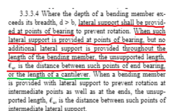
I guess the option provided by the WoodWorks was based on the clause (underlined by green) in the NDS :) Good to know it does exist.

Untitled_jkwcab.png
 
...that has nothing to do with the inflection point. A pure cantilever doesn't have an inflection point - the green underline is just talking about the physical length of the cantilever.

The WoodWorks option allows the user the set the unbraced length as the distance between points of zero moment (inflection points in the beam's curvature), which would be a direct violation of what you underlined in red (that a physical lateral support is required to adjust the lu).
 
@phamENG,

No offense, this is for discussion only.

NDS 3.3.3.5 specifically specifies the unbraced length of the single-span beam and cantilever beam. That's the reason that leads me to believe that "or the length of a cantilever" means the length between end bearing (M-max and the zero bending moment, which is a cantilever alike, but avoid spelling out "inflection point" to avoid confusion.

Untitled_pd9bon.png
 
3.3.3.5 is referring to the effective length. Effective length (le) and unbraced length (lu) are two related but different things. For a deep dive on the difference, start with AWC Technical Report 14.

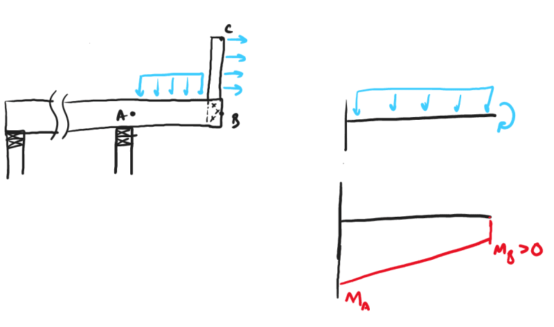
For one thing, the end of a cantilever is not always a point of zero moment, though it often is:

Screenshot_2022-06-23_130046_adyjr6.png


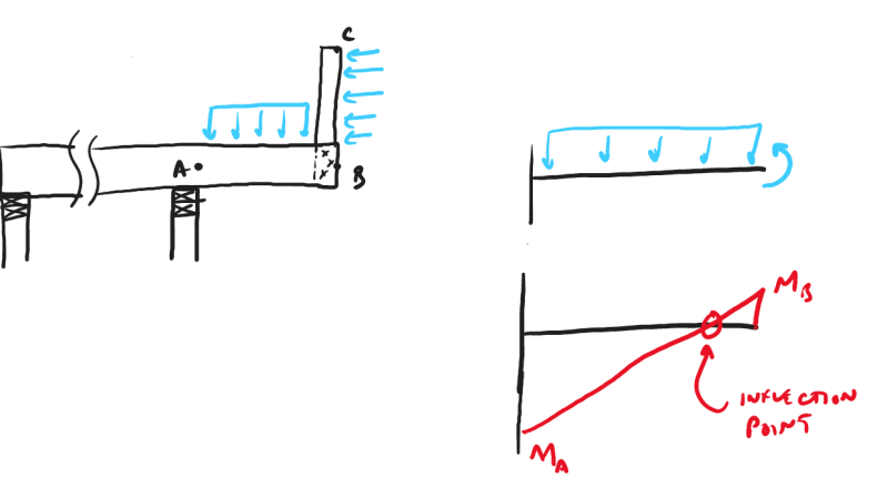
And for another, the cantilever end won't have an inflection point unless you apply a moment to the end that is in the opposite direction of the bending moment from a uniform load:

Screenshot_2022-06-23_130443_jyldep.png


So if you were to select that woodworks option, it would only mess up the analysis of a cantilever for a unique case like this one since most cantilevers do not have inflection points. But it would screw up all sorts of continuous beam analysis models where it would see the unbraced length as significantly less than the actual unbraced length.
 
@phamENG,

I suggest digging into WoodWorks to see the reasoning for providing such an option. Maybe they will refer back to TR 14 :)

So, so far we don't see a code provision that clearly/openly permits the use of the inflection point as a brace point. Agreed?
 
I think the use of the inflection point as a point of restraint is a mistake that comes from cases where the member is continuously restrained. If you have floor continuously restraining the top flange then the last point of restraint on the critical flange once the moment reverses occurs at the inflection point.
 
Yes it’s the restraint immediately beyond the inflection point that most codes allow you to count. With 99.9% of structures have something framing into the beam it ends up much the same. But yeah, an inflection point per se provides no restraint.


This thread came up when I was trying to check the interweb for the Galambos reference:
thread507-320359

I believe that is the CSA methodology although maybe it's not explicitly codified. Off the top of my head, CISC's wording is [paraphrase] "use a rational method to determine the effective length of the cantilever". So then you have to dig into references and such, Galambos's "Guide to Stability Design Criteria" being one of the major ones.

Andy Metten's steel book has a small blurb on it (lifted from the Galambos table) and there could very well be included in the CISC's DM3 for "Gerber Roof Girders" but don't quote me on that.

 
skeletron you remembered correctly. I took Andy's structural steel course and he has this right in his lecture notes as well.

Cap1_ogfjf8.jpg


Cap2_azhkcu.jpg
 
I can't comment on what your code says. But a inflection point has never been a braced point against LTB buckling. If a code has ever used this approach it has been wrong.

I did some research into this awhile back (when I was a tech support engineer for RISA). We had users complain that the program didn't automatically consider the inflection point as a brace point. I had to nicely explain to them that the code did NOT allow for that. Ergo, my desire to research this so that I could respond more accurately.

I'm pretty sure the AISC 2nd edition (circa 1994) specifically mentioned that this was not allowed. However, years before that the AISC stability seminars had been saying the same thing. So, we're probably talking about mid 1980's that AISC was trying to educate the engineering community about this.

Now, there are some caveats to this point. Yes, engineers had been traditionally using the inflection point as a point of bracing. But, most people who were doing that were also taking Cb equal to 1.0. So, they weren't taking advantage of the non-uniform moment along the unbraced length to increase their member strength.

So, when engineers would complain that there are boat loads of structures out there designed considering points of inflection as brace point I would point out to them that if they took Cb = 1.0, then they unconservative error about the unbraced length was hopefully balanced out by their conservative Cb assumptions.

 
Anyone who really like "stability" topics and wants to better understand the basis of the various codes and why the differ slight for different countries, I would highly recommend the SSSR Guide to stability that Enable showed in his last post.
 
phamENG said:
For one thing, the end of a cantilever is not always a point of zero moment, though it often is:
Screenshot_2022-06-23_130046_adyjr6_cijjgd.png

And for another, the cantilever end won't have an inflection point unless you apply a moment to the end that is in the opposite direction of the bending moment from a uniform load:
Screenshot_2022-06-23_130443_jyldep_wdrflt.png
Shouldn't these bending moment diagrams (the red lines) be nonlinear instead of linear?
 
@hoshang, The thoughts/messages delivered by the rough graphical representations are clear and have been delivered through. Good enough.
 
Status
Not open for further replies.

Part and Inventory Search

Sponsor