Eng-Tips is the largest engineering community on the Internet

Intelligent Work Forums for Engineering Professionals

Understanding complex input and output in frequency response FEA 1

Status
Not open for further replies.

BioMes

Bioengineer
Nov 2, 2022
40
0
0
PL
Hello everyone!

I'd like to understand the meaning and practical interpration of complex input and output in harmonic/frequency response FEA.

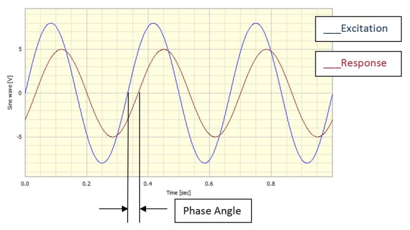
Let's start with input - each load in this type of analyses can be defined with an imaginary component (F=F_Re+iF_Im). From what I've read, it's out-of-phase load. But what does it mean in practice? Does it always correspond to phase angle of 90 degrees so when one sine wave is at zero, the other one is at its peak as shown here?

It makes sense when there are two loads (like Fx with real component and Fy with imaginary component) - then the aforementioned two sine waves are time variations of both loads. But what when there's only Fx with real (in-phase) and imaginary (out-of-phase) component?

Now when it comes to output, which is much more complicated - it can be expressed in two different forms - magnitude and phase angle or real and imaginary. As I understand, magnitude simply means amplitude of the sine wave of the response. Phase angle is more tricky. Is it just the offset between the two sine waves (load and response) like in the picture below?

fig10_jclofh.jpg


Source:
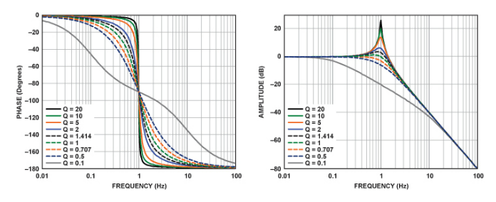
And is it true that a phase angle of 180 degrees corresponds to the case when sine waves are opposite (when one is at its peak, the other one is at its trough as shown on the first referenced website)?

Real and imaginary representation of the results is the most difficult to understand for me and the referenced blog post doesn't really help. I would assume that real is the same as mangitude in the first representation but I can be wrong. What about the imaginary part? Could you explain its practical/physical meaning in simple words?

I've also heard that a phase angle of 90 degrees corresponds to natural frequency. Is it really the case? Why?
 
Replies continue below

Recommended for you

All mechanical structures will have at least one resonant frequency in each axis depending. The stiffness must raise the frequency to limit the displacement that has a 2nd order attenuation with rising frequency. The acceleration transfer function can be defined by the classic 2nd order equation and modelled by an RLC low pass filter simulated here. There are many sites which represent these equations.

I use the Falstad site below for filters where you can adjust any RLC value with the mouse wheel or keyboard by selecting the item (edit). The Q factor is the gain and impedance of the resonant stored impedance over the load R at resonance. Lord shock mounts using Solothane have a Q of 5. ( as I recall)


Options> Show Phase (enable)

The phase is 0 deg at low f and -180 deg past the resonance and -90 deg at resonance.
 
Inputs - pretty arbitrary for one sine wave, it's just the phase of the sin wave at t=0.

Yes the phase of a transfer function is the phase difference between the excitation and the response

is it true that a phase angle of 180 degrees corresponds to the case when sine waves are opposite (when one is at its peak, the other one is at its trough as shown on the first referenced website)? yes

Your understanding of R and I is incorrect. R=mag*cos(theta) I=mag*sin(theta) (high school maths)

I've also heard that a phase angle of 90 degrees corresponds to natural frequency. Is it really the case? Why?

bode-sdof_qtdi8i.png


In very simple systems yes, in more complex systems almost never. The reason for the phase at resonance is easily understood if you look at the Transfer Function of a SDOF system with broadband excitation in the Argand or Nyquist plane, real vs imaginary. Then compare it with the TF of a 2 DOF modelwith damping and the two resonances fairly close in frequency


Cheers

Greg Locock


New here? Try reading these, they might help FAQ731-376
 
Thank you for the replies.

@sunnysky

I know that complex numbers are used in electrical engineering too since sine wave signals are also considered there but this branch of engineering is completely unfamiliar to me and I'm just focusing on mechanical vibrations to understand the practical/physical meaning of those quantities in context of FEA.

@GregLocock

So what does the time variation of a single load (e.g. Fx) with real and imaginary component look like? Is it a combination of sine and cosine wave or just sine wave starting (at t=0) already from 90 degrees (peak) instead of 0 degrees? But then what would the number assigned to imaginary part mean? Like F=F_Re+iF_Im where F_Re=100 and F_Im=70. And btw. does specifying only the real part mean that the load has time variation in form of a cosine wave? I always though it was the opposite.

And I also have some doubts regarding real and imaginary output, the rest is clear thanks to you. So basically real is a cosine wave and imaginary is a sine wave? That's also what I've read somewhere but then I forgot about it when I was writing the first post. And the numbers reported by the FEA software as e.g. imaginary stress are amplitudes of cosine waves while real ones are amplitudes of sine waves?
 
Thanks again, now input is clear to me. Maybe with a small note - I guess that it would be sine wave (imaginary) + cosine wave (real) and hence the phase angle of 90 degrees, right?

Is what I wrote about output (that real output = cosine wave while imaginary output = sine wave and that values reported in the real/imaginary format are amplitudes of those waves) in the previous post correct?
 
I'd have to say that the phase of the fourier of single signals is not all that meaningful, it's just telling you where you are in the cycle when you started sampling the data.

" I guess that it would be sine wave (imaginary) + cosine wave (real) and hence the phase angle of 90 degrees, right?"

Wrong, or at least, incomprehensible. You don't get two waveforms, you get a sinusoid, or cosinusoid, of a magnitude, phase, and period. That's it. Yes, you can decompose it into a sin wave and a cosine wave starting at t=0=theta=0, but mathematically it is the same. sin(A + B) = sinA cosB + cosA sinB , A is a constant (you are calling it phase) and B is w*t. Again, high school maths.


Cheers

Greg Locock


New here? Try reading these, they might help FAQ731-376
 
Yes, I was actually thinking about a single wave but initially defined as two waves (real=cosine and imaginary=sine=90 degrees phase angle offset) by the user and then combined into a single wave by the solver. As you said, for that single wave it’s hard to apply the phase angle concept in a meaningful way so I stick to the explanation with two waves combined into a single one.

Can you confirm that the rest of what I wrote before (mainly about output) is correct? So basically different outputs mean:
- magnitude - combined amplitudes of real and imaginary waves
- phase angle - offset/lag between input and output waves
- real - amplitude of a cosine wave
- imaginary - amplitude of a sine wave
- value at an angle - combined real and imaginary values at a given time/location along the curves (expressed in form of a phase angle) - real only for the angle of 0 and imaginary only for the angle of 90

As I understand, output signal can also be expressed as a single wave (like what I described above about input) but it’s often broken into two waves to operate on both real and imaginary components.
 
- magnitude - combined amplitudes of real and imaginary waves -yes with pythagoras
- phase angle - offset/lag between input and output waves -yes
- real - amplitude of a cosine wave -yes if phase is defined as zero when t=0
- imaginary - amplitude of a sine wave -yes if phase is defined as zero when t=0, but it might be -1 or +1
- value at an angle - combined real and imaginary values at a given time/location along the curves (expressed in form of a phase angle) - real only for the angle of 0 and imaginary only for the angle of 90 -yes, as in the equation i gave


Cheers

Greg Locock


New here? Try reading these, they might help FAQ731-376
 
Status
Not open for further replies.
Back
Top