Eng-Tips is the largest engineering community on the Internet

Intelligent Work Forums for Engineering Professionals

Understanding delta VT ratios 5

Status
Not open for further replies.

veritas

Electrical
Oct 30, 2003
467
0
0
AU
Hi

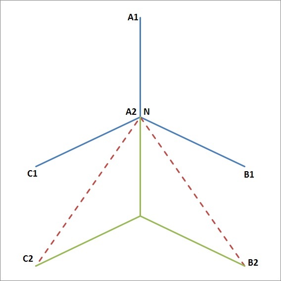
I have come across a 11kV VT which has one 33kV primary winding, one three-phase secondary winding and one delta winding. Ratios are given as [11kV/SQRT(3)]:[110V/SQRT(3)]: [110V/3].

I am comfortable with the ratios of the three-phase windings being [11kV/SQRT(3)]:[110V/SQRT(3)] which boils down to 100:1.

But I cannot understand where the 110V/3 comes from for the delta winding. The way I see it the open-delta voltage is the sum of the 3 phase voltages, VA + VB + VC = 3V0 = 0 with a healthy system. With a fully blown EF (say on A phase), VA is missing and so output is VA. This would be 63.5V and the primary side on the A-phase is 33kV/SQRT(3) which leads to 100:1 again? So why 110V/3?

Thanks.
 
Replies continue below

Recommended for you

waross said:
The directed resultant of two equal voltages displaced by 120 degrees will be an equal voltage displaced by 240 degrees from the reference voltage. 110 Volts.

The two voltages will have an angle of 60° between them - 110V∠30° + 110V∠-30° = 190.5V.

This is why the VT rating is typically 110/3V rather than 110/√3V on the the delta winding - it gives a nice 110V during a fault (63.5∠30° + 63.5V∠-30° = 110V), which is a more typical level for voltage relays.
 
Under normal conditions you have three windings displaced 120 degrees and developing 63.5 Volts each, summing to zero.
With the loss of one phase, you have two windings displaced 120 degrees and developing 63.5 Volts each, summing to 63.5 volts.
With one phase grounded, that phase is shorted out and develops zero Volts. The other two phases now develop 110 Volts each, summing to 110 Volts.

Bill
--------------------
"Why not the best?"
Jimmy Carter
 
You've missed the change of angle that occurs due to the fault.

Refer to the below diagram of the primary voltages. The blue line is pre-fault system, the green line is the post-fault system (fault is A-phase to earth).

Broken_Delta_dbjh6n.jpg


Before the fault, the angle between VB1-N and VC1-N is clearly 120°, and the magnitude (not drawn) is 6.35 kV.

When the fault occurs, VA moves to N, so VB and VC also shift to compensate, which is why VB-N and VC-N magnitudes are now 11 kV. It should be visually apparent that the angle between VB2-N and VC2-N (both shown as dashed red lines) is a lot more acute than previously - if you do the trig, it is now 60°. This same change in angle occurs in the secondary as well, hence why we are adding two voltages that are 60° apart, not 120°, giving an "extra" factor of √3, hence why the veritas's VT has a ratio of 6350:36.7 not 6350:63.5 on the broken delta-connected winding.
 
mgtrp, My understanding is like this. When a LG fault is there in A phase voltage collapses in that phase, but other phases will see line to line voltages(assuming unearthed system).So secondary voltages will be 110/3 x root3. But the angle between the secondary voltages in healthy phases 120 degrees. So the voltage across the lines of these phases 110/3 xroot3xroot3 =110V.
 
It's interesting that IEC 60076 part 1 defines Open Delta as:-
3.10.3
open-delta connection
the winding connection in which the phase windings of a three-phase transformer, or the windings for the
same rated voltage of single-phase transformers associated in a three-phase bank, are connected in series
without closing one corner of the delta

Whereas the IEEE 100
The Authoritative Dictionary of
IEEE Standards Terms
open-delta connection (power and distribution transformers)
A connection similar to a delta-delta connection utilizing
three single-phase transformer, but with one single-phase
transformer removed.

Regards
Marmite
 
I couldn't find any hand written examples so I spent my evening writing on an example trying to derive a solution to the OP's questions:
However, purely from a phase domain perspective how can the output voltage be 110V? I still believe it is 110/3. If I'm wrong I'd very much like to know how.
The key thing here is whether the system is grounded or not (ungrounded, hiZ-grounded).

I think the OP have got a really good answer from "mgprt" for an ungrounded network. If the network is effectively (solid) grounded things are different.
I'll attach my scribbles since it consider both scenarios and also include some calculations. Someone might enjoy them...

-BAK
 
 http://files.engineering.com/getfile.aspx?folder=51c3514c-1f8d-4e45-8aa8-66f4b0106063&file=thread238-405639_r0.pdf
Thanks Marmite. That question has come up before in discussions between the 50 Hz group and the 60 Hz group. (mostly)

Bill
--------------------
"Why not the best?"
Jimmy Carter
 
Your nocturnal efforts are very much appreciated. Thank you. Reading through your calcs helped me to sort out all the cobwebs that were causing my confusion.

The vector diagram posted by mgtrp actually nicely illustrates the "neutral inversion" that occurs. When the EF occurs on an impedance system the potential of the neutral point actually goes negative w.r.t. ground.

I think this an excellent thread and a good refresher if nothing else. I would like to thank all respondents.

Regards.
 
Looking at the vector drawing, A1, B1, C1, N; A line to ground fault on A1 will shorten the vector A1-N. A1 will approach N. If there is no interaction between the phases, N will not go negative. A zero impedance fault will result in A1 meeting N.
As mgtrp pointed out, The connection of the PTs is C1-A1-B1. As a fault on A1 brings A1 towards N, the phase angles of the PTs approach C1-N-B1
Most of my delta experience has been with power transformers. Full delta, 3 transformers; Broken delta, 3 transformers, and open delta, two transformers. I'll skip 3 pages of descriptions of the problems and just say that I am not a fan of delta secondaries for power transformers.

Bill
--------------------
"Why not the best?"
Jimmy Carter
 
ShooterBooter

There is one small thing - on page one of your calcs, should the Vb and Vc line to ground voltages not be 11kV and not 11kV/sqrt(3)?

Need to think more about waross' comment.
 
Veritas,

Yes, you're right. Actually that part should indicate the pre-fault conditions. I'll correct that and post a new verion later today. I also need to correct the calculations on page two; I'm missing a "3" in the middle part. It doesn't affect the outcome though.

-SB
 
Thanks for that ShooterBooter. Something else that occurred to me - let's say the 11kV network is fed from the delta winding of a star-delta transfomer. There is a source at the other end of the 11kV network from where the 11kV earthing point is usually provided. But this has tripped off and so the 11kV network is effectively unearthed. Being delta there is no physical neutral point but a virtual one.

I thus ask myself is your pre-fault vector diagram still applicable? i.e is the virtual star point at ground potential. I would say yes in that the system has a reference point via the earth of the primary neutral winding. There is no fault and so your pre-fault phasor diagram looks okay to me.

Comments?

waross - regarding your last post, you are referring to the VT voltage vectors. I was referring to the primary system neutral - i.e. star point of a transformer winding. Let's suppose the 11kV winding supplying our network in question is a star winding and let's suppose it is earthed via a NER = R ohms. With an EF current flows from the ground through R and to the neutral point N. From there back to the fault via the faulted phase. Current flowing through R necessarily implies a volts drop across R and since current flows from the Ground to N via R, means that N must be at a lower potential than Ground - thus the term "neutral inversion".

The VT will not see this as it's neutral is solidly earthed. So whatever current flows in the VT neutral, no neutral inversion here. All the VT will effectively see is O volts on the faulted phase and sqrt(3) * Vnom on the healthy phases.

Or so I think??
 
Hi Veritas,

I'm not 100% sure that I follow your first question fully, but if your source that's providing the grounding trips off on the 11 kV side, then you now have an ungrounded system. If it trips off on the HV side, then it will continue to provide a ground reference.

For your second question, you are correct that there is some voltage between the neutral point and ground, but not correct that it is "negative" - this is an AC system, so the voltage between the two is constantly changing. All of the vector diagrams are constantly rotating.
 
Hi mgtrp,

Yes, the 11kV network will be ungrounded once the source with the earth point gets disconnected. My 11kV delta winding in essence is now connected to an unearthed network.

Regarding the 2nd point - I have to disagree here. Please do not get confused between instantaneous and rms values. I am referring to rms quantities whe I refer to current flowing in the neutral. When we say a source delivers a current of say 100A to a load then we represent this as an rms current flowing from source to load. With phasors we actually have the length of the phasor being the magnitude of the rms quantity and the direction is relative to a reference which is usually the A-phase voltage. Yes, phasors rotate but the relative angles between the phasor quantities remain the same (assuming all in synchronism).

 
Veritas,

The phasor diagram(s) can be thougth of as a representation of the VT windngs, nothing virtual about that.

Regarding the other issue of phasor voltage being negative; I would say no, it's not negative. IF it were negative the phasor arrow of phase "a" would point towards the neutral point. This would mean that the vector sum of the three phase voltages is non zero. This can't be, since we don't have any other voltage drop in the (ideal) system.

...and also another update of my document.

Regards,
 
 http://files.engineering.com/getfile.aspx?folder=942ff415-80f7-413a-b1f0-831e4c32af17&file=thread238-405639_r2.pdf
Status
Not open for further replies.
Back
Top