Continue to Site

Eng-Tips is the largest engineering community on the Internet

Intelligent Work Forums for Engineering Professionals

  • Congratulations waross on being selected by the Eng-Tips community for having the most helpful posts in the forums last week. Way to Go!

Understanding pressure in piping system for water flow in a 3 inch line vs half inch line 2

Status
Not open for further replies.

MAT73

Chemical
Feb 22, 2017
5
Hope you can help me with the following question. In a system that has a positive displacement pump supplying 500 liters/min of water into 3 inch tubing, how can I calculate the increase in a pressure that would occur if suddenly the flow was diverted to a 1/2 inch tubing diameter. Attached please find a diagram of the system.
I calculate that the velocity in the 3 inch tubing would be approximately 2 m/s; while for the same volumetric flow the velocity in the 0.5 inch tubing would be 120 m/sec.
If I were to have a manometer in the discharge of the pump (P1), I would assume that the pressure that I would read when the system is flowing through the 3 inch tubing will be much lower than when the system would switch to the 0.5 inch tubing. Since I have a positive displacement pump the volumetric flow rate would still be the same at 500 liters/min (or close to it since more slippage might occur).
The pressure relief valve in the pump is set to 8 barg so I want to calculate if when switching to the 0.5 inch tubing the pressure will cause the pressure relief valve to open or not.
Thanks in advance for any help / guidance you can provide.
 
 http://files.engineering.com/getfile.aspx?folder=43ec0958-82c2-4e7e-873f-eae3784749f3&file=Question_Flow_of_water_in_3_inch_vs_half_inch.pptx
Replies continue below

Recommended for you

The velocity in the 0.5" tubing is too high. It's closer to 70 m/s. I recommend using the Darcy-Weisbach Equation to calculate the increase in pressure, but you need to know the length of tubing in the run to do the calculation. Using 500 L/m:

0.5" has 21,000 psi/100 feet
3" has 1.9 psi/100 feet

Good luck,
Latexman

To a ChE, the glass is always full - 1/2 air and 1/2 water.
 
Pressure drop varies at a ratio of around (D1/D2) ^4 or sometime ^5 Note this is ID.

Therefore assuming ( probably wrong) that your ID ratio is similar to the OD ration you're looking at a pressure increase x 1000 to 1500.


So your flow will be no where close to 500l/min if the relief valve lifts at 8 bar. Maybe 10-15l/min?

Find a chart for your pipe pressure drop and work out a flow based on the length, elevation and max pressure you have.


Remember - More details = better answers
Also: If you get a response it's polite to respond to it.
 
You might be able to pass a maximum of 1 liter/sec through the 0.5 hose. The pressure relief will immediately release the pressure.
 
Or it might be 0.1 l/ sec. We know nothing about pressure when operating the 3 inch so don't know how much extra pressure there is or how long the 1/2 " tubing is. Males a massive difference.

All we know is what we get told. So far that isn't enough to ne able to put decent numbers t to anything

Remember - More details = better answers
Also: If you get a response it's polite to respond to it.
 
Yep, that's why I calculated dP / 100 ft.

Good luck,
Latexman

To a ChE, the glass is always full - 1/2 air and 1/2 water.
 
Thank you very much for the responses. It is clear to me, based on this, that the pressure relief valve will definitely open and therefore I will see a significantly smaller flow through the 0.5 inch tubing.

If you do not mind, could you help clarify some concepts that I always see when working flow problems.

1. When we are talking about a Pressure at the discharge of the pump measured with a manometer, this refers to "Static Pressure" (basically the force that the fluid is exerting over the pipe wall), while the "Dynamic Pressure" would be the result of the velocity of the flow (which could be calculated as half of the density times the velocity squared). "Static Pressure" + "Dynamic Pressure" equals the "Total Pressure". Is this correct?
2. When there is a reduction in the diameter of a pipe, the "dynamic pressure" increases while the "static pressure" decreases. It is the difference in the "static pressures" what is referred as the "deltaP", correct?
3. In the case of pumping a liquid with a positive displacement the maximum pressure (static pressure) would be right at the outlet of the pump, the "dynamic pressure" is a function of the velocity which as long as the pipe would have the same diameter the velocity should be the same. If I were to place a 2nd manometer 100 ft after the outlet of the pump, I would read a lower pressure (static pressure) due to the friction losses with the pipe; however the "dynamic pressure" would still be the same since the velocity of the fluid would be the same as in the outlet of the pump, correct?
4. It is very different if we were using a centrifugal pump since in that case, there would be a point as you move away form the outlet of the pump, there would be a point in which there would actually be no flow, both the Static and Dynamic pressure get to zero once you reach the maximum "head" of the pump, correct?

Thanks in advance for your help in clarifying these concepts.
 
Aaaah, you appear to have what I refer to as an "attack of the Bernouillis" here.

To address your issues see below.

1) In theory yes you are correct. However, for all practical purposes, the static pressure element of the total is >99% therefore the dynamic pressure or velocity head is, in practice, ignored for liquid flows. Unless you have a low density (air), a low static pressure (mm's of water column) and a high velocity (>10m/sec), just don't bother. However do the calc for yourself using units of pressure as Pa, density in kg/m3 and velocity in m/sec and see for yourself. Using you example, pressure is say 2 bar, 200,000 Pa and velocity of water 2 m/sec. Velocity head as a pressure is therefore 2000Pa = 1% of what is already a small number.

2) correct, but as noted above, the difference in static pressure due to changes in velocity is normally very low and over any appreciable length is dwarfed by frictional losses

3) Correct

4) Incorrect. Both pumps will provide a static pressure as you call it ( normally called discharge head or discharge pressure) to provide the energy to move the fluid along the pipe to a point of lower energy. the second the fluid leaves the pump it neither knows nor cares how it got to that level of energy and hence your supposition in item 3 is true for both a PD and centrifugal pump. don't ever forget conservation of mass. There is no way flow can be occurring in one part of a system without the mass flow balancing either by flow out or compression or reduction in pressure to balance mass into the system.

I think what you mean n 4 is that centrifugal pumps are in effect constant pressure machines and if you start to increase the flowing resistance or static head lift then the flow will reduce and if the static head you're asking the pump to undertake equals or exceeds the shut in head of the pump then flow will reduce to zero. PD puimps on the other hand, if no pressure relief is fitted, will try and pump a constant volume per unit time if all else remains the same and hence as you raise the static head or flow resistance, its pressure output rises until it exceeds the input torque / power of whatever is driving it at which point it stalls. This can result in very high pressures, hence the requirement for pressure relief systems in all PD pump applications.

Does that make it clearer??

Remember - More details = better answers
Also: If you get a response it's polite to respond to it.
 
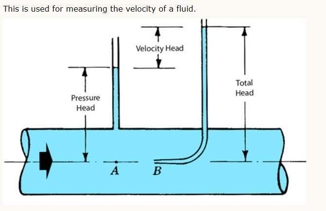
The total energy in the pipeline is the sum of the static, dynamic and hydrostatic pressures. The static pressure is the pressure as measured moving with the fluid that can be measured with a pressure gauge. The dynamic energy depends on the velocity head and will be relatively small. The hydrostatic pressures is the pressure due to the force of gravity

The velocity head can not be measured with a pressure gauge. You need a pitot tube to measure velocity head.

However, the hydrostatic pressure will depend on the elevation. If the pipeline is relatively level, the hydrostatic pressure will be constant. If there is significant elevation difference, then there will be differences in pressure due to the elevation. For those applications, the elevation head will have to be added to the static pressure.

Document127_pddvwn_pleikf.jpg
 
Thanks for both replies...very helpful!

LittleInch, you are right, I am suffering the "attacks of the Bernoullis" and Bernouilli is winning..... I am still not very clear on question number 4. For example if I had a centrifugal pump with discharge pressure of 3 bar and a flow of 100 kg/min and downstream the pump there is a valve and a second manoemeter right before the valve. If the valve was 100% open , I would see 3 bar in the discharge pressure at the pump and 100 kg/min and let's assume a 2.5 bar pressure in the 2nd manometer (basically due to friction losses) . However if the valve would start to close (let's assume a linear relation of flow vs. the % opening of the valve) if I had 50% opening, I would expect a 3 bar discharge pressure, 50 kg/min and half the velocity of the flow, and a pressure in the 2nd manometer a somewhat higher (for example 2.7 bar) since at lower velocity there would be less losses due to friction. I understand that you can close a valve when using a centrifugal pumps since basically there will be more slippage and will be less flow. Would this scenario be correct?

In the same scenario, if everything is equal but instead of having a centrifugal pump you have a PD pump. If the valve was 100% open , I would see 3 bar in the discharge pressure at the pump and 100 kg/min and let's assume a 2.5 bar pressure in the 2nd manometer (basically due to friction losses)same as withe the centrifugal pump. However if the valve would start to close (let's assume a linear relation of flow vs. the % opening of the valve) if I had 50% opening, would I see more than 3 bar pressure at the discharge, still 100 kg/min but now at a higher velocity since the valve is half open? The second manometer would also have a higher pressure vs when using the centrifugal pump, but still this pressure would be less than the pressure in manometer 1. Would this scenario be correct?

I would think there is a point in which as you continue to close the valve, the velocity of the liquid is not high enough to allow 100 kg/min to flow out and therefore the pressure in the whole system would spike to either the point in which the pump stalls or one of the elements in the system (e.g. valve, pipe) would literally fail due to the pressure.

Could you provide your perspective in this scenarios? Sorry , that I am a slow learner but still confused.
 
A few points.

A pump generates fluid flow. Pressure is the resistance to flow.

As you shut the valve, the centrifugal pump system pressure will increase to the shut off head of the pump.

As you shut the valve, the pd pump system pressure will increase until some system component fails.

(corrected)
 
Mat73.

First para basically correct. I would refer to pressure guage rather than manometer as these are normally used only to measure small pressures such as inches of water. Also as the flow reduces, a centrifugal pump will increase pressure by 5 to 10%.

3rd para. Basically correct if you're talking about the velocity inside the valve. You will at some point get to critical flow where the fluid is at sonic velocity.
2nD para basically correct, but the velocity in the pipe would be the same. Velocity in the valve would go up but that's not what you're setting at the second pressure tapping.

Bimr
With respect I disagree. A pump doesn't generate flow. It creates a higher energy state in the fluid. The system decides if there is flow. E.g if the system pumps water up a 100 M high hill. Your pump can only create 75m head. There is extra energy in the fluid but no flow.

2nd paris only true when theft is no flow. Flow at the same elevation will have different pressures when flowing due to frictional losses.


Remember - More details = better answers
Also: If you get a response it's polite to respond to it.
 
LittleInch,

There are many others that you also will disagree with:

"Note!!! A pump does not create pressure, it only creates flow! Pressure is a measurement of the resistance to flow."


"A pump does not create pressure, it only creates flow. The gauge pressure is a measurement of the resistance to flow."


"Note that the pump generates a fluid flow, and the fluid pressure is generated by the resistance that the flow meets when it flows through the hydraulic system."

 
Within a system a pump creates flow by creating a higher energy state at that point compared to some other point further away. This manifests itself as pressure. To say a pump doesn't create pressure or head is simply not true. What pray is the head of a pump when it is shut in?? There is no flow. So no head or pressure??

All of the attached quotes are only valid when looking at a flowing system where flow, pressure or head and friction all interact with each other. It isn't possible to say which comes first. Follow the energy.

If you take the last quote, the pump generates flow which generates resistance which generates pressure, Therefore the pump generates pressure....

It's really that the pump creates a higher energy in the fluid than it had when it entwred the pump by converting the input energy (motor, driver) into fluid energy (flow and head/pressure).

Remember - More details = better answers
Also: If you get a response it's polite to respond to it.
 
There are often different ways of explaining how things work which, ultimately are identical. There are energy balances that are equivalent to force methods.
"Higher energy state" is valid but somewhat abstract and theoretical. The only way for a fluid to have a higher energy state is to be hotter or to have higher pressure or velocity. The quibble here is does a pump create flow or pressure. If you look at a centrifugal pump as a black box then "higher energy" is an adequate explanation, but does nothing to explain how the pump works.

In University there were there fundamental classes in ChemE: heat transfer, mass transfer, and momentum transfer. Pumps, fluid flow, and viscosity were covered in momentum transfer. A centrifugal pump operates by spinning fluid in a volute using an impeller. It is giving the fluid momentum (and thus energy). If the pump is deadheaded the fluid comes up to the speed of the impeller. There is flow in the pump but not outside of it. The centrifugal force of the spinning water creates a higher pressure at the outside of the volute than at the center. This spinning water only took energy to accelerate, but once spinning does not need any further energy except for frictional losses, which are a small percentage of the acceleration energy.

So getting to the very fundamentals of a centrifugal pump, it first creates flow (which is higher energy). The reason that momentum transfer is the best way to describe a centrifugal pump is that momentum is conserved in nature whereas kinetic energy is not. Total energy is conserved but the complication of accounting for where every bit of energy went is very complicated and not useful for explaining how a pump works..
 
Compositepro,

Thanks for response and I get where you're coming from. I quite like the higher energy bit as it gets away from this chicken and egg situation about flow and pressure. Sure the very initial rotation of the impellor will generate flow, but pressure rise follows within a very short period. It is not practical to separate flow and pressure, IMHO.

To get flow you need pressure change. The magnitude of the pressure required to move the fluid is dependent on the system design, friction, viscosity etc, but without a pressure difference (after accounting for all elevation changes), you won't have flow.

I think it is quite simple to use the fact that the pump creates both flow and pressure simultaneously, with the magnitude of the pressure or flow coming from the downstream system design.

We seem to have lost the OP in the process of this discussion so not sure if we've moved things forward for Mat73 or not.

Remember - More details = better answers
Also: If you get a response it's polite to respond to it.
 
Status
Not open for further replies.

Part and Inventory Search

Sponsor